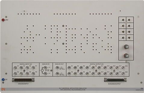
PLC universal application simulator

Simply combine the universal PLC application simulator with any of the various PLC applications and circuits (analog and digital) to implement practical exercises with very little installation. The experiments are based on a standard syllabus. The application simulator is equipped with switches and pushbuttons as sensors as well as LEDs and an electronic circuit to simulate actuators. Process feedback signals (e.g. feedback signals from the contactors) are generated automatically. To simulate movements, levels and positions there are 3 running lights integrated into the device. The individual experiments are ready to perform after the overlay masks are fitted.
- 8 digital inputs (actuators)
- 20 digital outputs (sensors)
- 2 analog inputs (actuators)
- 2 analog outputs (sensors)
- 3 running lights
- Connections realised on 4mm safety sockets
- 1 37-pin sub-D male connector (input signals) for the connection to PLC via system connector
- 1 37-pin sub-D socket (output signals) for connection to the PLC via the system connector
- Operating voltage: DC 24 V / 0.3 A
- Size: 456 x 297 x 125 mm (WxHxD)
- Weight: 1 kg
If the models for the universal plant simulator are connected to the control systems via discrete wiring and not via the 37-pin cable, it is sufficient for the controller to have 8 digital inputs and 8 digital outputs. If models are connected via the 37-pin system plug connectors, the associated programmable logic controller needs to have at least 20 digital inputs and 8 digital outputs. The PLC must in any event possess two analog inputs and outputs.