


Quadripoles and Filters
UniTrain training system for passive filters and resonant circuits: students build high-pass, low-pass, band-pass and band-stop circuits, measure cutoff frequencies with the Bode plotter and determine resonance and Q factor.
- Defining filter parameters
- Representing the transfer function in the complex plane
- Determining transfer characteristics
- Analyzing band-pass and band-stop filters
- Modular concept with safety extra-low voltage
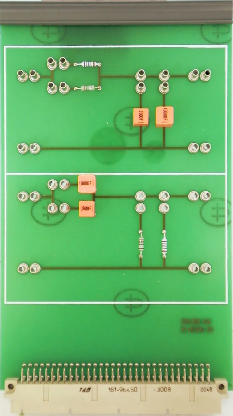
- RC High-Pass and Low-Pass experiment card
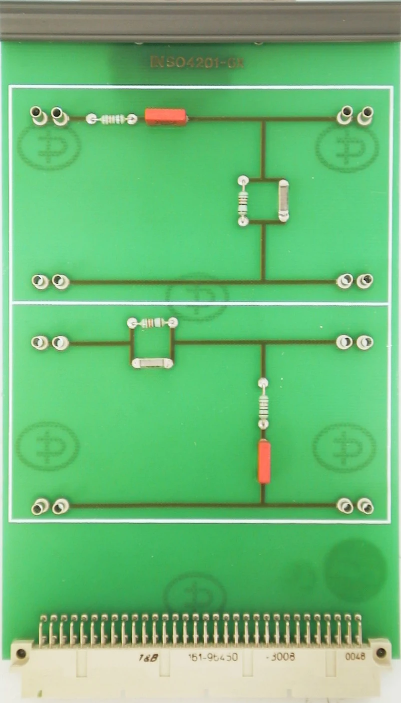
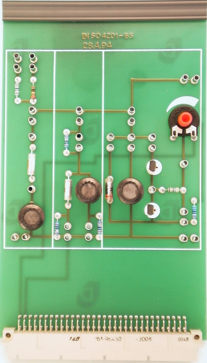
- Band-Pass/Band-Stop experiment card
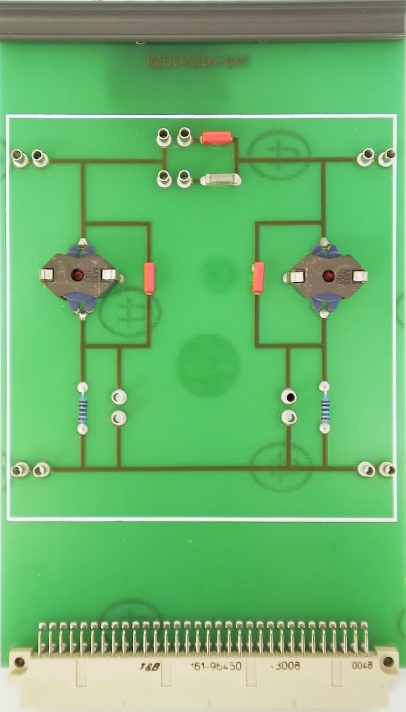
- Band Filter experiment card
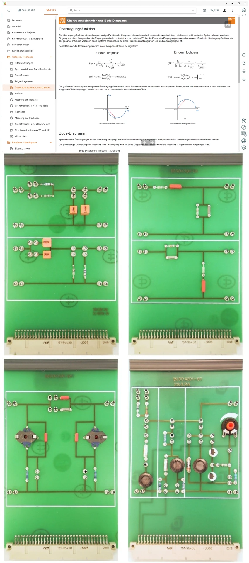
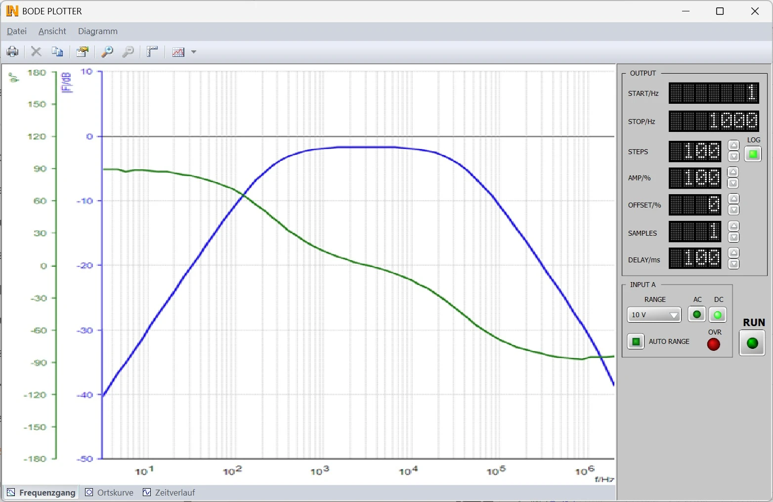
Filters separate frequency mixtures, suppress interference signals and make selective signal processing possible. This UniTrain training system lets students build the corresponding circuits themselves. On the high-pass and low-pass card, bridging plugs create nine filter combinations whose amplitude and phase response is recorded by the Bode plotter, allowing the cutoff frequency to be read off at -3 dB. On the band-pass and band-stop filters, students determine the center frequency and bandwidth and compare the measured values with their calculations. On the band filter, they vary the capacitive coupling of two parallel resonant circuits; on the resonant circuits, they measure resonance, voltage magnification and Q factor and tune the resonant frequency using a varactor diode.
| Course | |
| CO4204-9A | Course Telecommunications 1: Quadripoles and filters |
| Accessories | |
| CO4203-2A | UniTrain Interface mit virtuellen Instrumenten (Basis VI) |
| CO4203-2J | UniTrain measurement accessories, shunts and connection cables |
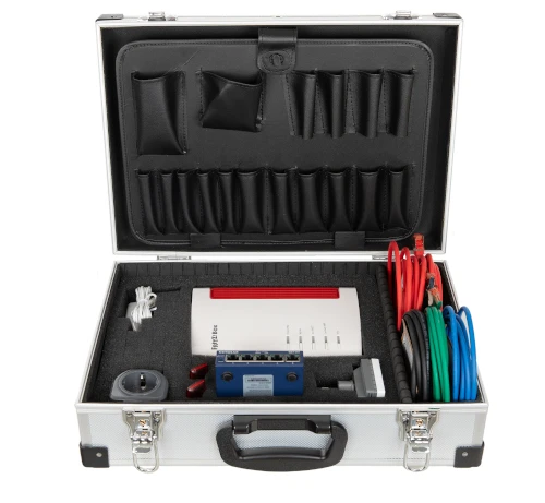
| CO4203-2Y | UniTrain storage case for one UniTrain system |
| CO4203-2B | UniTrain Experimenter |
Learning Content in Detail
Defining filter parameters
Representing the transfer function in the complex plane
Determining transfer characteristics
Analyzing band-pass and band-stop filters
Investigating coupling behavior
Measuring the resonance of resonant circuits
Calculating Q factor and bandwidth
Trying out varactor diode tuning
Features & Applications
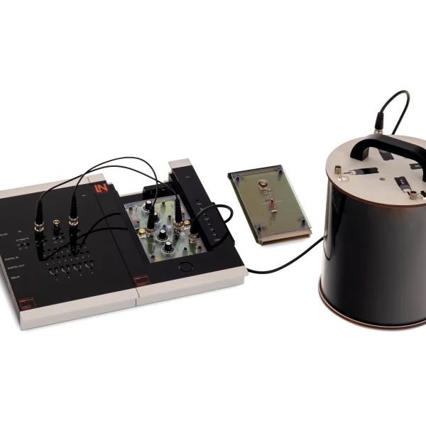
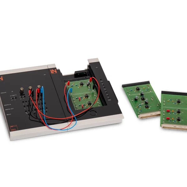
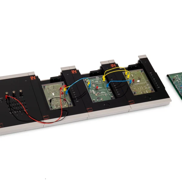
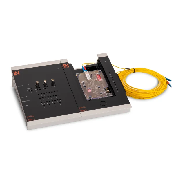
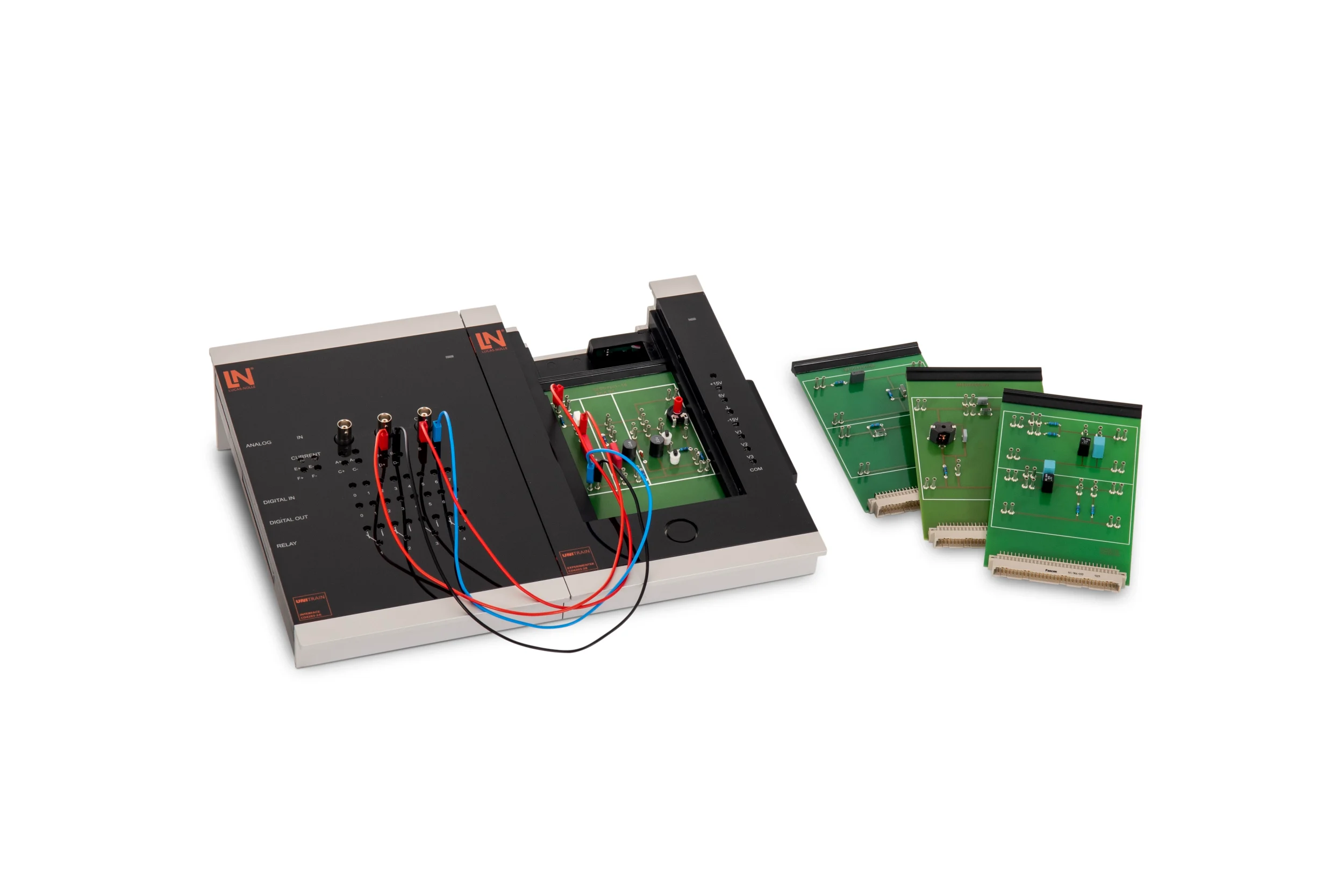
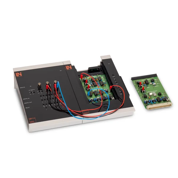
- Modular concept with safety extra-low voltage — The experiment cards are plugged into the experimenter. All measurements take place in the touch-safe extra-low voltage range.
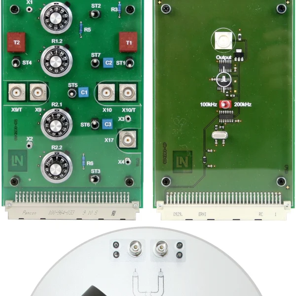
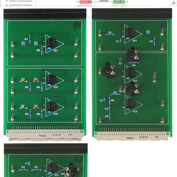
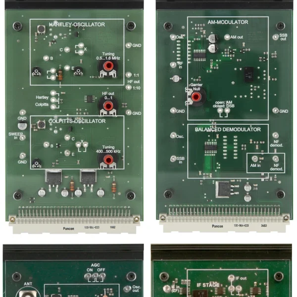
- RC High-Pass and Low-Pass experiment card — Contains separate RC low-pass and high-pass sections. Bridging plugs allow nine different filter combinations to be wired.
- Band-Pass/Band-Stop experiment card — Contains first-order RC band-pass and RC band-stop circuits for investigating center frequency and attenuation behavior.
- Band Filter experiment card — Provides two capacitively coupled parallel resonant circuits with the same resonant frequency and variable coupling via 5 mm shorting jumpers.
- Resonant Circuits experiment card — Contains a series resonant circuit, a parallel resonant circuit and a parallel resonant circuit with varactor diode tuning for resonance measurements.
- UniTrain interface — Provides all the measuring instruments and sources required for the experiments as digital instruments.
- Bode plotter — Automatically records amplitude and phase response from 1 Hz to 5 MHz and displays the Nyquist plot in the complex plane.
- Frequency tuning via a varactor diode — Students vary the DC voltage at the varactor diode and determine the tuning range of the resonant frequency of a parallel resonant circuit.
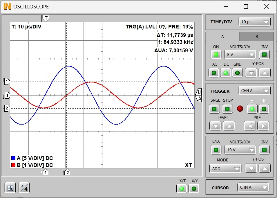
- 2/4-channel oscilloscope — Displays the input and output signals in X/T or XY mode and measures phase shift, amplitude and frequency using cursors.
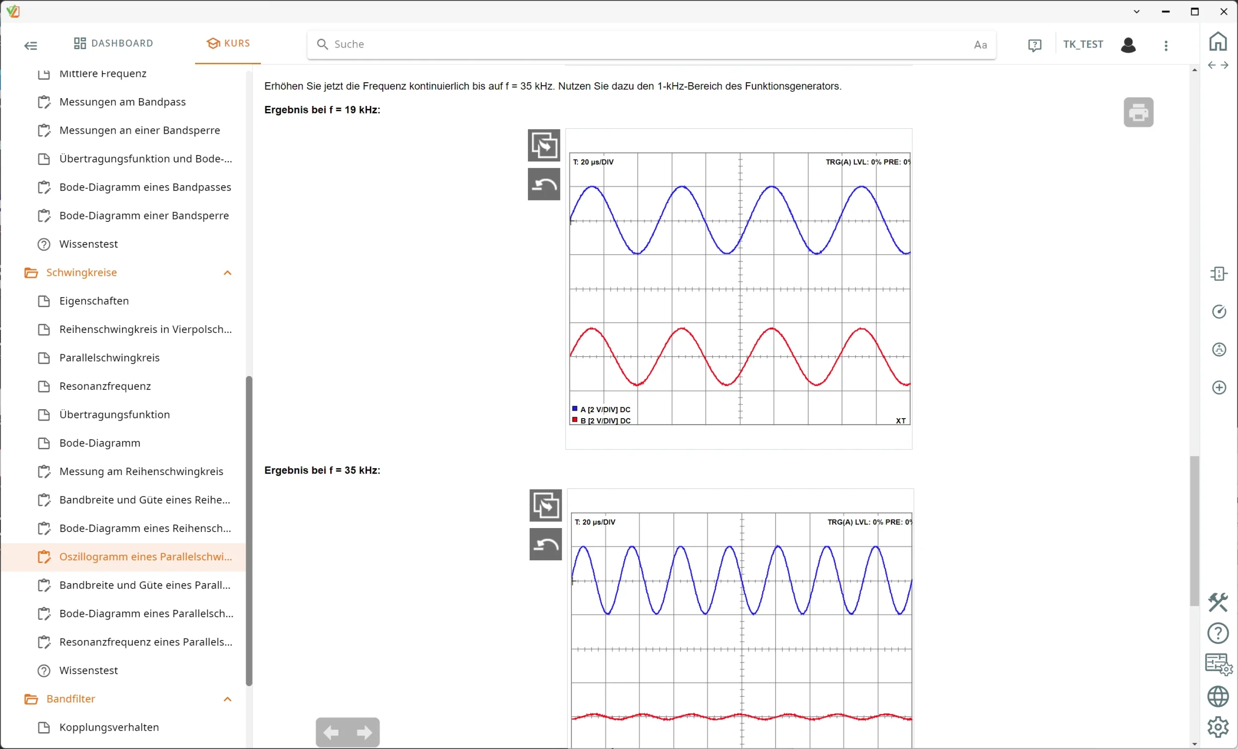
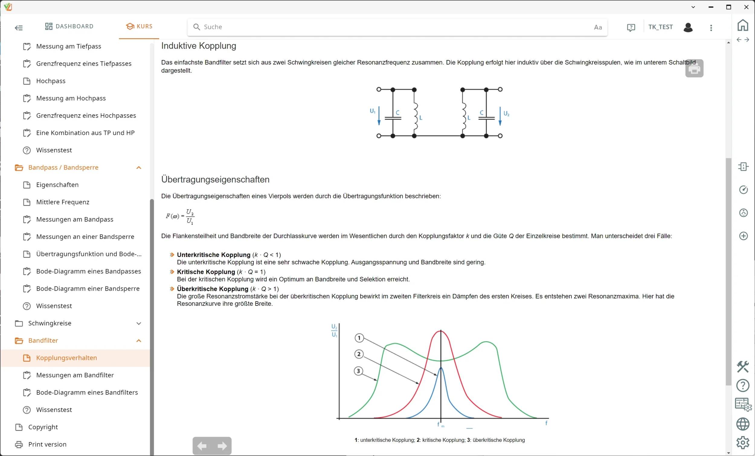
- LabSoft course software — Guides students through the experiments, teaches the theory of two-port networks, offers knowledge tests and saves the recorded measurement curves.
- Characterizing RC low-pass and RC high-pass filters — Students vary resistors and capacitors, take measurements in the time domain, analyze the amplitude and phase response with the Bode plotter and determine the cutoff frequencies.
- Analyzing RC band-pass and RC band-stop filters — Students investigate the selectivity of frequency-dependent voltage dividers, determine the center frequency and bandwidth and compare the measured values with the theoretical values.
- Investigating coupled band filters — Students vary the capacitive coupling of two parallel resonant circuits using shorting jumpers and observe how the passband and bandwidth shift as a result.
- Measuring resonance in series and parallel resonant circuits — Students determine the resonant frequency, measure voltage and current magnification and determine the Q factor as a function of the loss resistance.

From Knowledge Comes Capability.
You guide the learning
Where theory and practice go hand in hand.
RXLea brings a new way of learning: project-based, hands-on and clearly structured. Learners solve real-world tasks, while instructors save time on preparation. Interactive modules, smart analytics and real hardware create a modern, efficient learning world.
Hands-on and interactive
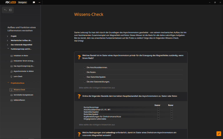
Animations, interactive tasks and realistic scenarios build a deep understanding. All content is organized into clear learning paths for focused, hands-on learning.
Digital support
3D assembly animations and digital instructions simplify complex procedures, reduce errors and help learners work more independently.
Visual support
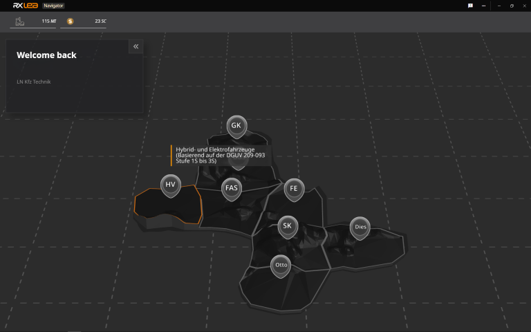
Overview graphics, screenshots and sample animations make the learning world transparent. Photos from the learning packages are also available, including country-specific versions where needed.


Stay ahead in
technical training.
Get the latest training systems, product launches and educational insights, delivered directly to your inbox.