

Skip to content

LIN Bus in Automotive

RXLea
Digital projects for hands-on learningInteractive learning content, directly connected to the training system.

LIN Bus in Automotive

ALB23UT

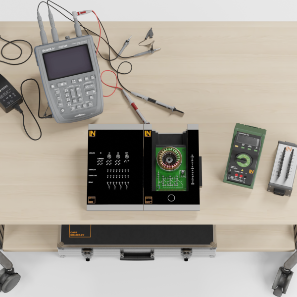
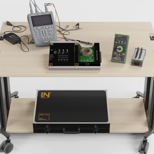
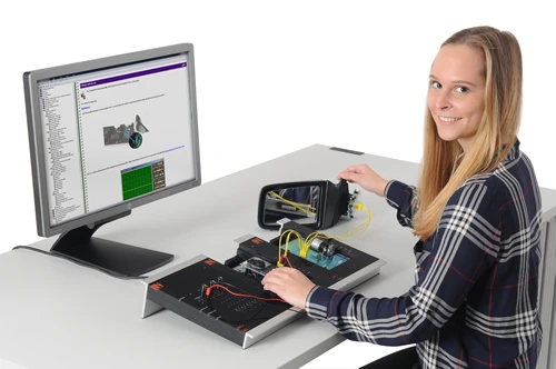
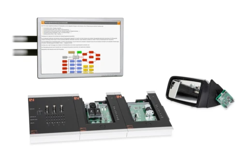
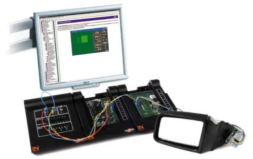
Learners master signal generation, protocol structures and systematic troubleshooting in LIN sub-buses. The training system offers hands-on diagnostics on real vehicle components from the comfort and convenience area.

Learning Content
  • Checking signal generation
  • Analyzing message structure
  • Data transmission rates
  • Identifying protocol fields
KEY FEATURES
  • Wiring harness representation
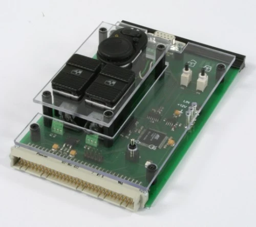
  • Power window rocker switches
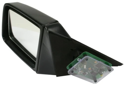
  • Movable exterior mirror
  • Signal asymmetry circuit
Speak with a Product Specialist +1 (757) 808-5696 · sales@lucas-nuelle.com

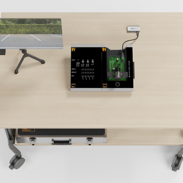
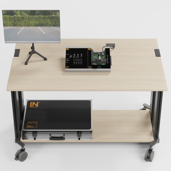
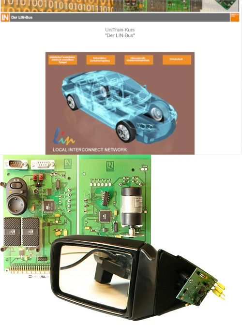
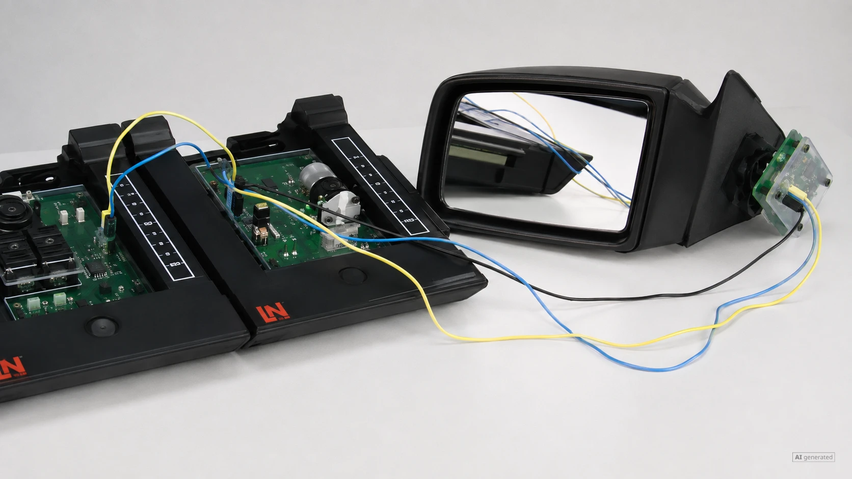
The increasing density of functions in modern vehicles calls for low-cost sub-buses. With this UniTrain course, learners gain a precise understanding of master-slave access control. The system is based on the physical coupling of a master control unit with intelligent slave actuators via a serial single-wire line. On the real door model, learners control the mirror or power window and read out the data traffic via the software monitor. In this way, they acquire in-depth knowledge of fault diagnosis and measurement technology on single-wire bus systems in automotive comfort and convenience electronics.

CO4204-7ECourse: LIN bus in automotive
CO4203-2AUniTrain Interface mit virtuellen Instrumenten (Basis VI)
CO4203-2JUniTrain measurement accessories, shunts and connection cables
CO4203-2YUniTrain storage case for one UniTrain system
CO4203-2BUniTrain Experimenter

Learning Content in Detail

With this system, learners acquire sound expertise in automotive bus technology. The practical experiments prepare them optimally for real-world service shop requirements.

Checking signal generation

Learners precisely check the recessive and dominant voltage levels on the single-wire data line.

Analyzing message structure

Learners visually distinguish the master’s message header from the slave’s message content.

Data transmission rates

Learners use the bit time to determine the difference in speed between the LIN bus, low-speed CAN and high-speed CAN.

Identifying protocol fields

Learners measure the duration of the synchronization break, address field and data bytes in the oscillogram.

Master-slave principle

Learners demonstrate that communication only starts when the master explicitly requests it with a header.

Tamper protection

Learners assess how the LIN bus is protected against unauthorized external switching commands from outside the vehicle.

Reading out data traffic

Learners read out hexadecimal data fields in the LIN monitor and assign them to the switch positions.

Systematic fault diagnosis

Learners isolate software-inserted line faults through targeted comparisons of setpoint and actual voltage waveforms.

Features & Applications

Discover the system’s practical hardware components and digital analysis tools. Real vehicle components and intelligent software enable efficient fault diagnosis.
  • Wiring harness representation — The board compares the 7-wire mirror wiring with the 3-wire bus cable. Learners immediately see the savings in material.
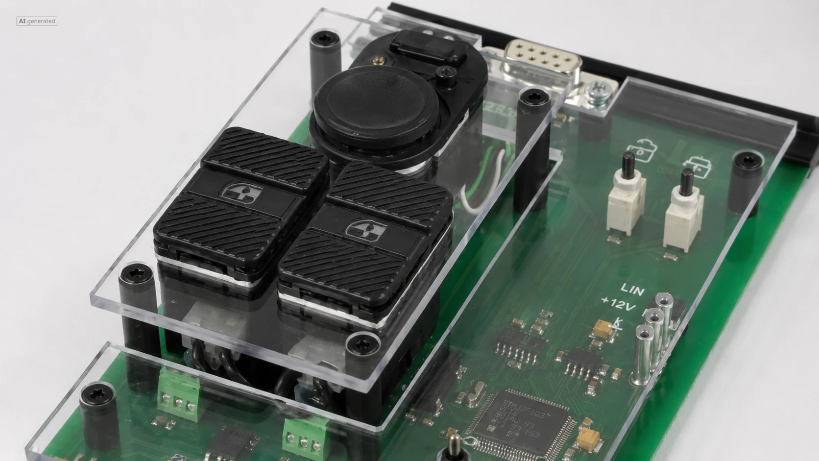
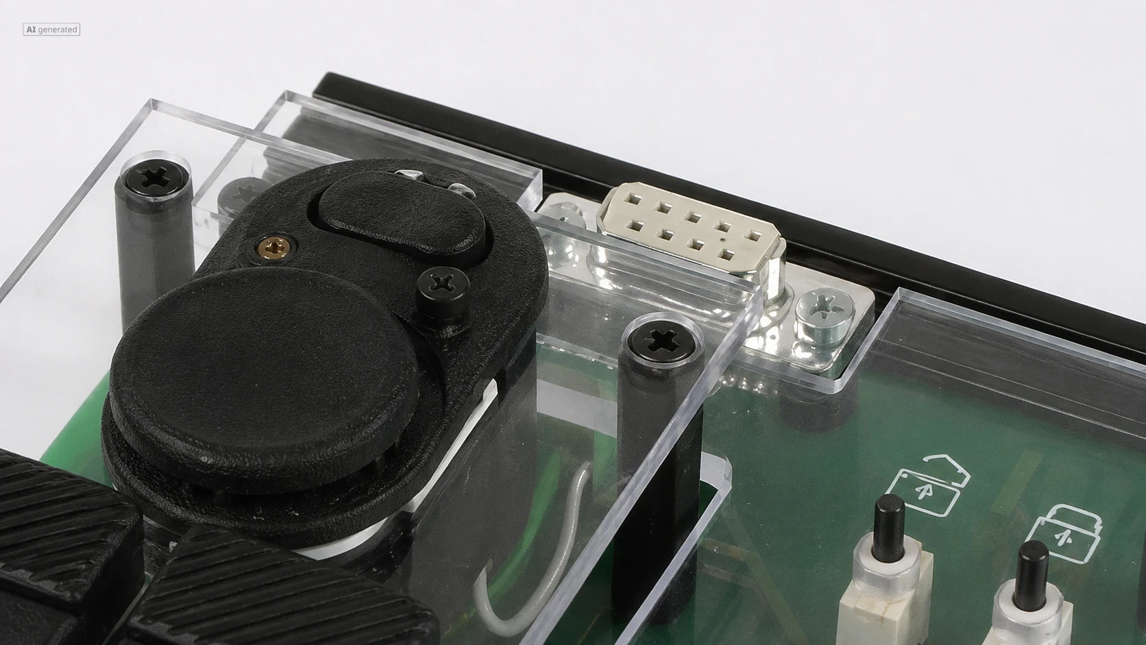
  • Power window rocker switches — Two toggle switches activate the DC motor. Learners operate the rockers and trigger visible changes in the direction of rotation.
  • Movable exterior mirror — The system integrates a real mirror housing. Learners observe the mirror physically tilting immediately after the bus command.
  • Signal asymmetry circuit — A rotary control inserts artificial contact resistances. The oscilloscope shows an asymmetrical drop in the levels.
  • Master control unit — The card simulates the door control unit with mirror joystick, central locking button and turn signal toggle switch.
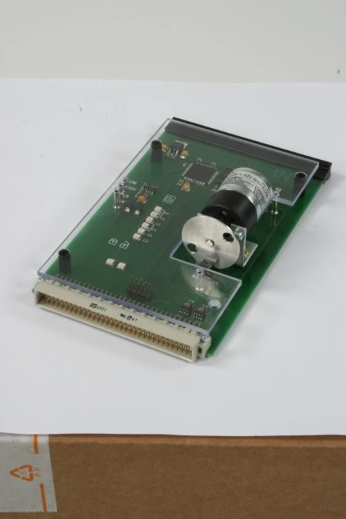
  • Slave power window card — The module contains the motor and a gear segment. A potentiometer serves as a sensor for detecting the window position.
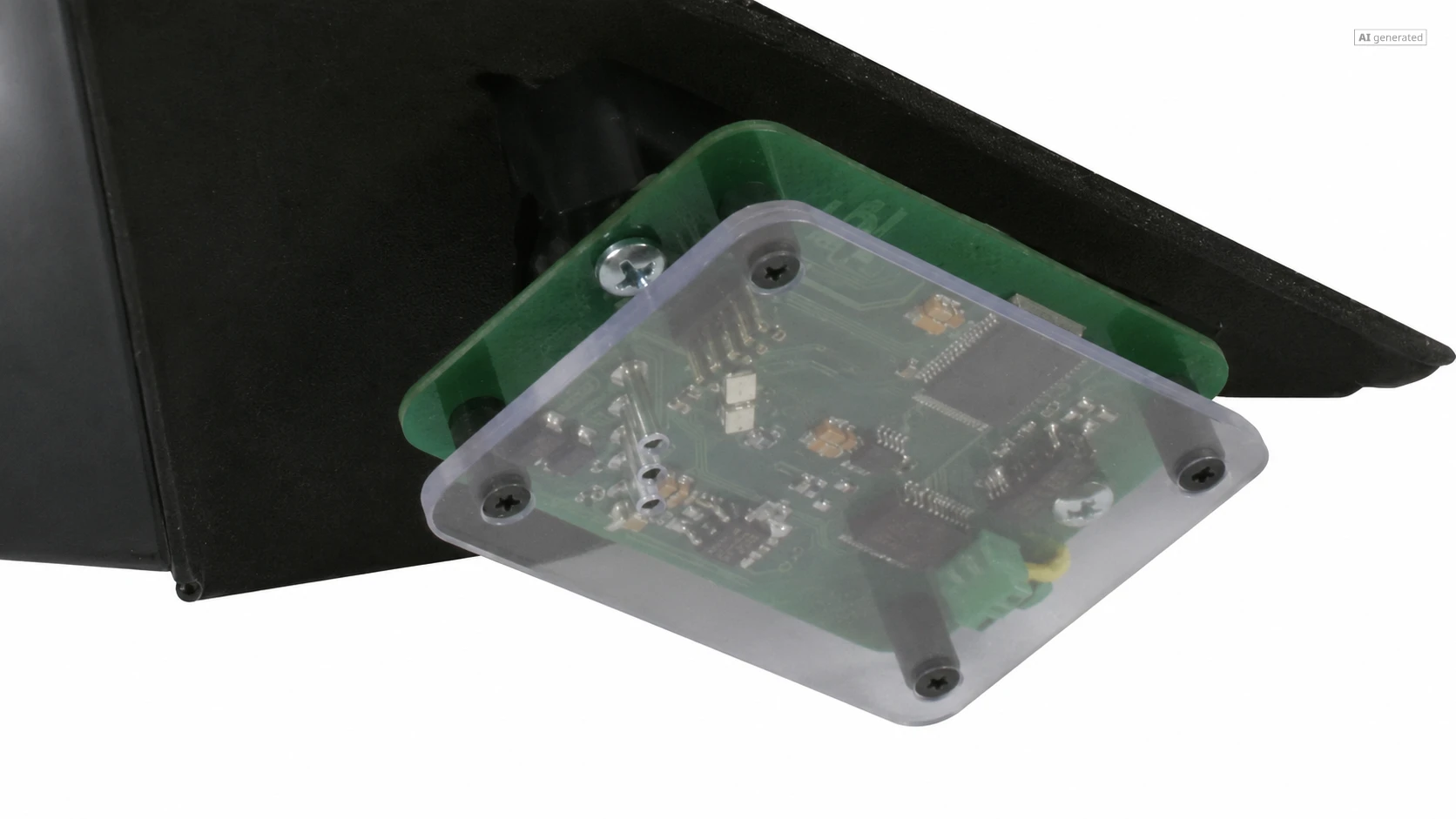
  • Mirror slave board — The board sits on the mirror base. LEDs flash brightly to indicate transmit and receive operations visually.
  • Transceiver output stage — The output stage shows the circuit. It pulls the bus voltage down to ground (dominant) or blocks (recessive).
  • Real-time protocol analyzer — The instrument decodes the single-wire data stream live. Learners read identifiers and data bytes from the color-coded display.
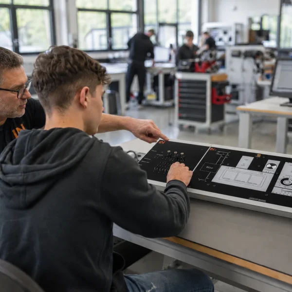
Learners working with RXLea on a tablet at a Lucas-Nuelle training system
RXLea

From Knowledge Comes Capability.

You guide the learning

Where theory and practice go hand in hand.

RXLea brings a new way of learning: project-based, hands-on and clearly structured. Learners solve real-world tasks, while instructors save time on preparation. Interactive modules, smart analytics and real hardware create a modern, efficient learning world.

Hands-on and interactive

Animations, interactive tasks and realistic scenarios build a deep understanding. All content is organized into clear learning paths for focused, hands-on learning.

Digital support

3D assembly animations and digital instructions simplify complex procedures, reduce errors and help learners work more independently.

Visual support

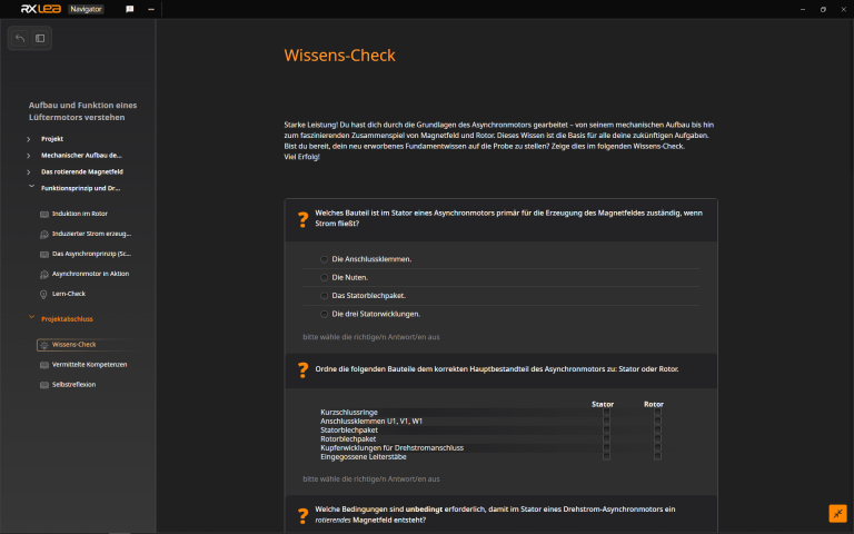
Overview graphics, screenshots and sample animations make the learning world transparent. Photos from the learning packages are also available, including country-specific versions where needed.

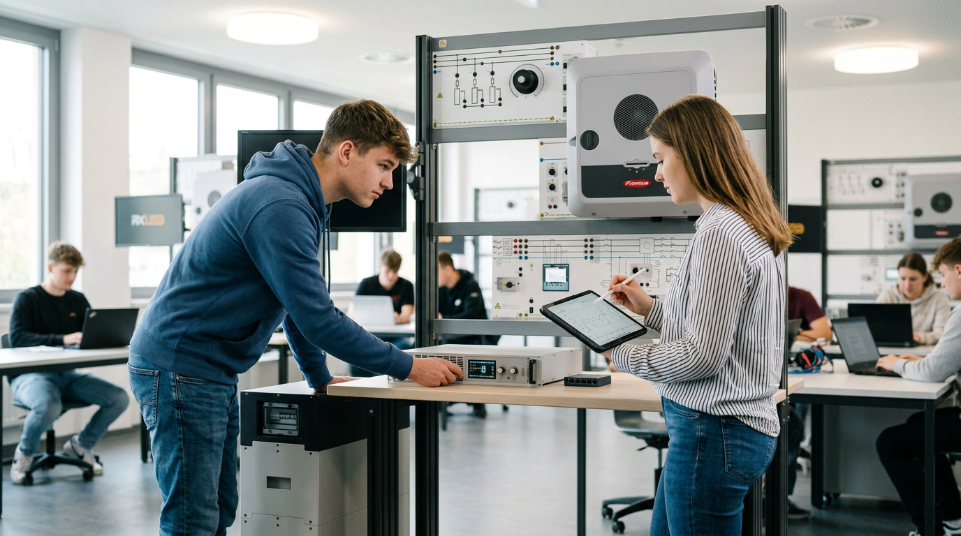
Learners using a tablet at an energy training system
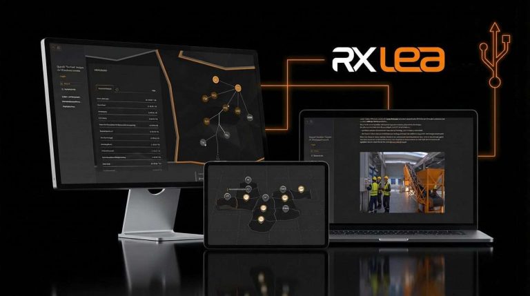
RXLea on desktop, laptop and tablet
RXLea Path Creator for building learning journeys
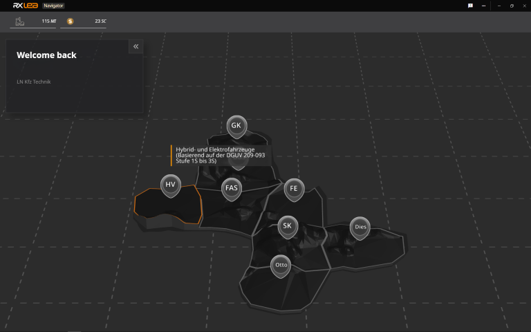
RXLea Navigator showing the learning world
Learn more about RXLea
Newsletter

Stay ahead in
technical training.

Get the latest training systems, product launches and educational insights, delivered directly to your inbox.

Your email address

By subscribing, you agree to our Privacy Policy. You can unsubscribe at any time.

 Please select at least one category before subscribing.
I'm interested in - select all that apply