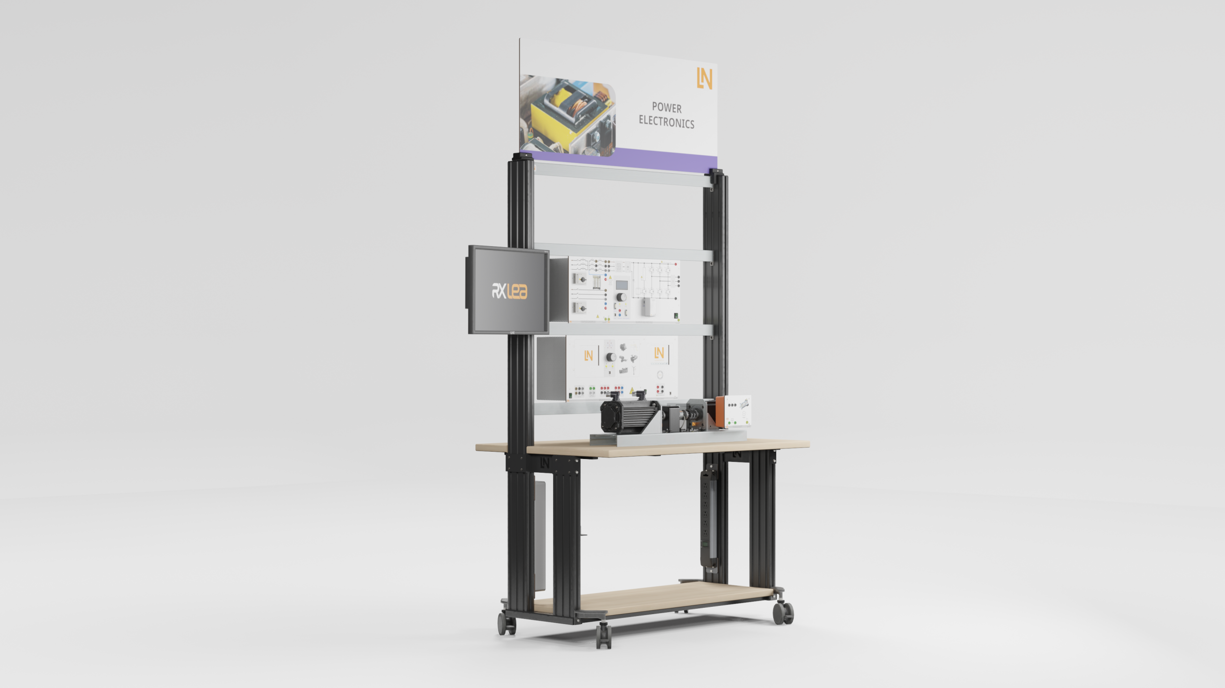



Controlled Permanent Magnet Servo Drive Using MATLAB – Simulink 300W
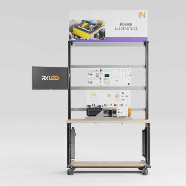
Hardware-in-the-loop training system for modeling and field-oriented control of PMSM using Matlab®/Simulink®.
- Setting up hardware-in-the-loop systems
- Implementing the Clarke and Park transformations
- Evaluating position information
- Optimizing cascaded controllers
- Model-based design and rapid prototyping
- Analyzing the Clarke and Park transformations
- Dimensioning current and speed controllers
- Implementing space vector modulation
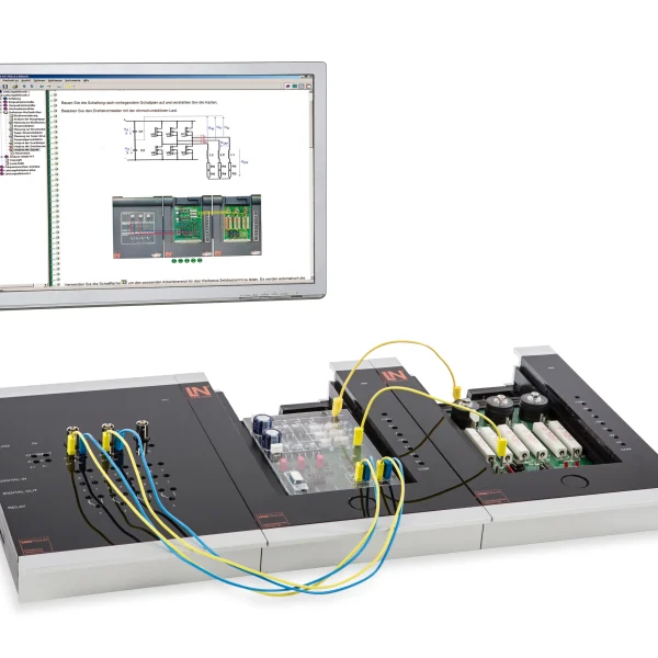
Thanks to their dynamic performance and efficiency, permanent-magnet servo motors are the physical heart of modern robotics and automation technology. In drive development, their control is created using a model-based approach: model-based design with MATLAB/Simulink is the established standard there for rapid prototyping and code generation. This is exactly the path that students follow on this system. They design the control algorithm in Simulink, generate real-time code, load it onto the power converter and use it to control the real servo motor. In doing so, they implement the Clarke and Park transformations and space vector modulation, calibrate the position encoder and compensate for the angular offset. Finally, they superimpose simulated and measured signals in the time diagram and explain the deviations.
| Base Product | |
| CO3636-3D | USB adapter with MATLAB toolbox for power electronics and process control |
| SO2805-1Q | Interactive Lab Assistant: Servo drives using MATLAB-Simulink 0.3 kW |
| SE2682-3S | Permanent Magnet Synchronous Motor (PMSM) 0.3 kW |
| SE2683-3T | Incremental position encoder 1024 pulses, 0.3 kW |
| SE2662-7C | Coupling guard with LED lighting for 300W machines |
| SE2662-2A | Rubber coupling sleeve, 0.3kW |
| SO2805-1M | Interactive Lab Assistant: Servo motors, electronically commutated motors 0.3 kW |
| CO3636-3B | Self-commutated converter circuits |
| Power Supply | |
| CO3636-3E7 | 3-Phasen Trenntransformator 300VA |
| Measuring Instruments | |
| CO5127-2A | Power-Multimeter |
| Accessories | |
| CO3636-6X7 | Dynamic servo machine test stand for 300W machines incl. control software ActiveServo 2.0 |
| SE2662-2A | Rubber coupling sleeve, 0.3kW |
| SE2662-7C | Coupling guard with LED lighting for 300W machines |
| Furniture | |
| ST8010-4G | Keyboard adapter for flat screen monitor holders |
| ST8008-8N7 | Protected power distribution for workstations |
| ST8010-4J8 | Multiple power outlet strip, 6 outlets, US-standard |
| Furniture Accessories | |
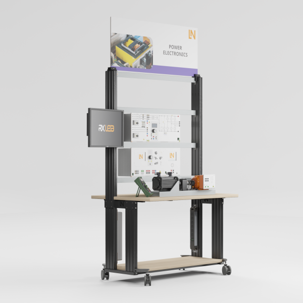
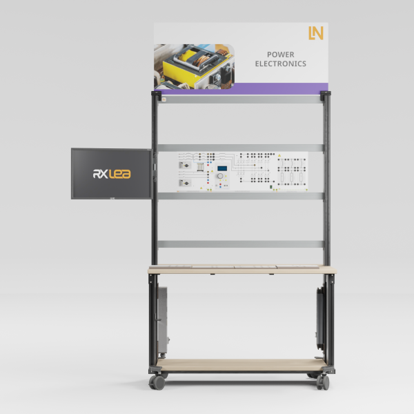
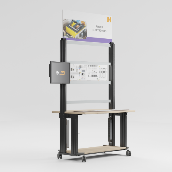
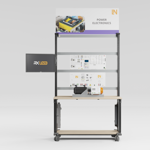
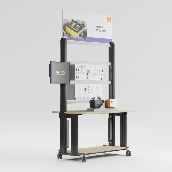
| ST8000-5B | Display for Power Electronics equipment |
| Measurement Leads | |
| SO5148-1L | Set of safety measurement cables, 4mm (31 leads) |
| SO5126-3R | Safety connecting plug 4mm with tap (2x), black, 1000V/32A CAT II |
| SO5126-3V | Safety connecting plug 4mm with tap (2x), blue, 1000V/32A CAT II |
| SO5126-3W | Safety connecting plug 4mm with tap (2x), green/yellow, 1000V/32A CAT II |
Learning Content in Detail
Setting up hardware-in-the-loop systems
Implementing the Clarke and Park transformations
Evaluating position information
Optimizing cascaded controllers
Evaluating simulation quality
Features & Applications
- Model-based design and rapid prototyping — Students develop the control structure on the PC, generate real-time code at the click of a mouse, load it onto the power converter and use it to control the real hardware directly.
- Analyzing the Clarke and Park transformations — Students investigate the transformation from stator-fixed to rotor-fixed coordinate systems. Using Simulink blocks, they calculate the d/q currents for field-oriented control.
- Dimensioning current and speed controllers — The PI controllers are designed at the continuous-time design level. Students test the settling time and overshoot in response to load steps virtually and then on the real system.
- Implementing space vector modulation — Students control the inverter’s IGBTs via modulator blocks. They analyze the pulse patterns generated and the sinusoidal current waveform.
- Aligning motor position and encoder system — Students calibrate the incremental encoder to determine the rotor position exactly and compensate for angular offsets in order to achieve maximum torque.
- Comparing simulation and reality directly — In the time diagram, students superimpose the simulated signals on the real-time measured values of the real drive and analyze the deviations in behavior.
- Self-commutated power converter with HIL capability — The control unit with a 6-pulse IGBT inverter and integrated DSP processes the generated Simulink code in real time and uses it to control the real machine.
- USB adapter with MATLAB toolbox — The electrically isolated interface exchanges parameters and measurement data between the Simulink model and the power converter during operation, in both directions.
- Synchronous servo motor 0.3 kW (PMSM) — The permanent-magnet motor serves as a highly dynamic test object. The electronic nameplate assists with parameterizing the motor models.
- Incremental position encoder — The encoder detects the rotor position with 1024 pulses. Students evaluate the signals in the DSP and use them to calculate the rotational frequency.
- Servo machine test system as an active load — Students emulate load steps and measure the mechanical torque. This allows them to test the control response of the Simulink controllers they have designed themselves.
- Tool-free coupling and temperature protection — The machine under test and the brake are coupled without backlash and without tools. An integrated temperature contact protects the motor against thermal overload.
- Shaft cover with safety interlock — The Makrolon cover shields the rotating parts. The status LED lights up green only when there are no faults, and only then does the system enable the power supply.
- MATLAB toolbox from Lucas-Nülle — Students use tailored Simulink blocks, for example for the Clarke transformation or IGBT control, allowing them to get from the model to an executable algorithm more quickly when designing drives.
- Live scope via the USB connection — Students access the DSP during operation. They record rotor-fixed currents, phase voltages and speed in real time and adjust controller parameters at runtime.
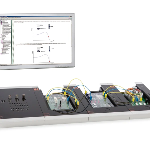
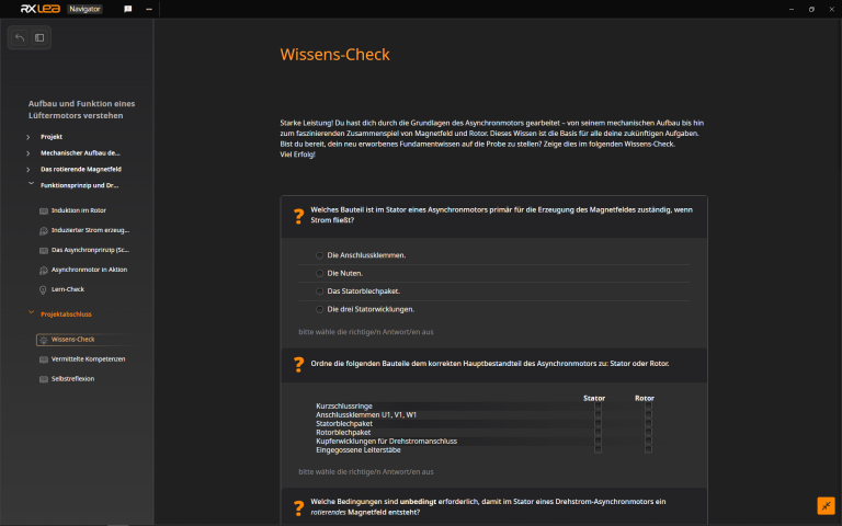
- Interactive Lab Assistant — The software guides students through the design process using multimedia. Students derive mathematical models, answer knowledge questions and compare their simulation results.

From Knowledge Comes Capability.
You guide the learning
Where theory and practice go hand in hand.
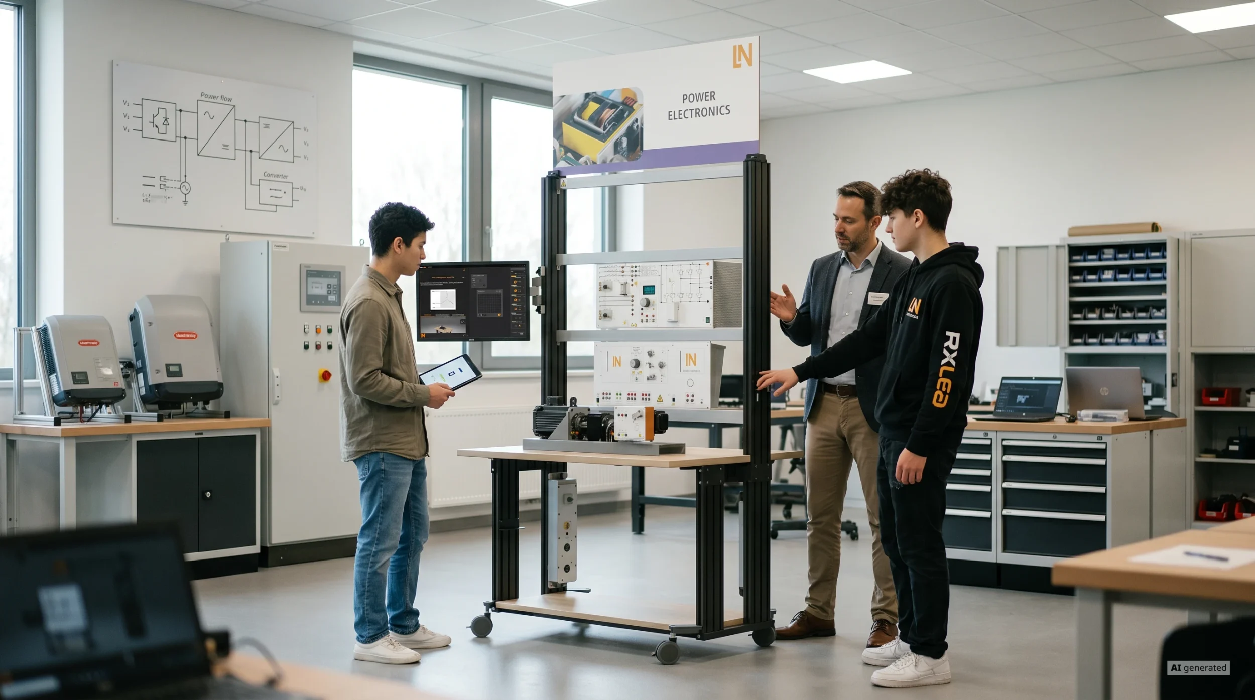
RXLea brings a new way of learning: project-based, hands-on and clearly structured. Learners solve real-world tasks, while instructors save time on preparation. Interactive modules, smart analytics and real hardware create a modern, efficient learning world.
Hands-on and interactive
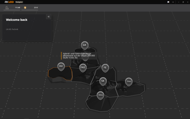
Animations, interactive tasks and realistic scenarios build a deep understanding. All content is organized into clear learning paths for focused, hands-on learning.
Digital support
3D assembly animations and digital instructions simplify complex procedures, reduce errors and help learners work more independently.
Visual support
Overview graphics, screenshots and sample animations make the learning world transparent. Photos from the learning packages are also available, including country-specific versions where needed.


Stay ahead in
technical training.
Get the latest training systems, product launches and educational insights, delivered directly to your inbox.