

Skip to content

Rotor Earth-Fault Protection

RXLea
Digital projects for hands-on learningInteractive learning content, directly connected to the training system.

Rotor Earth-Fault Protection

EGP31PT

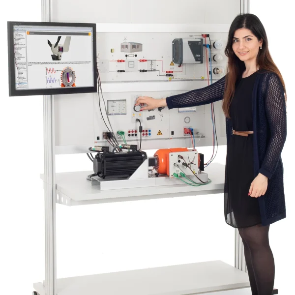
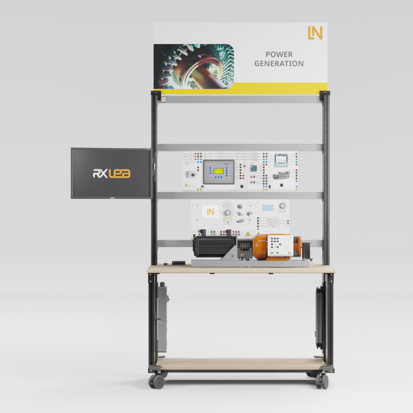
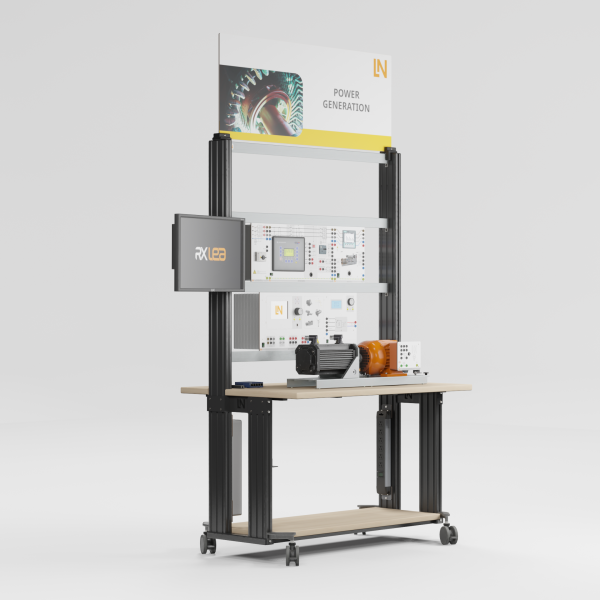
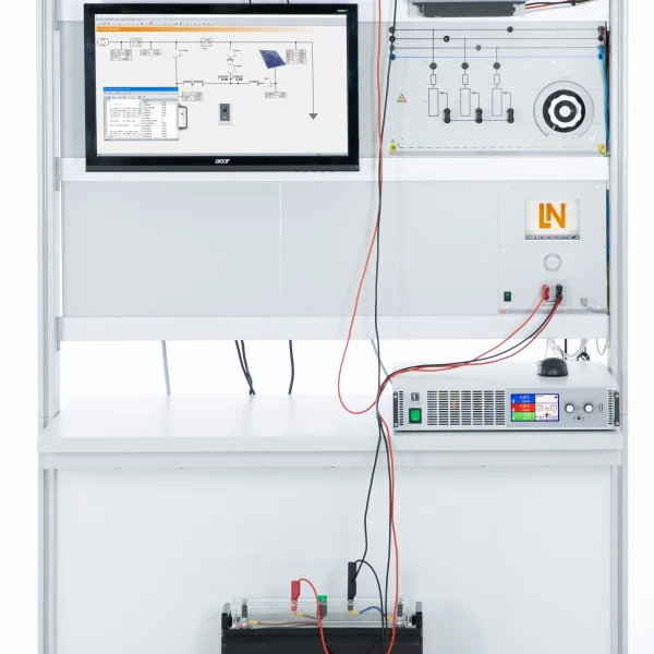
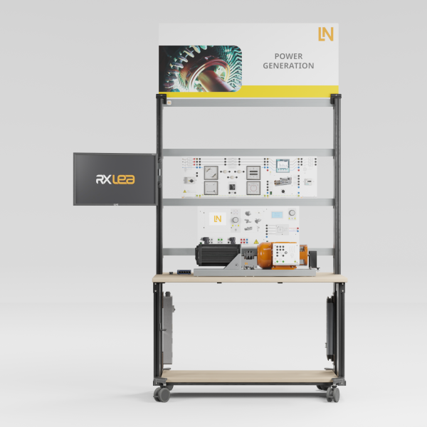
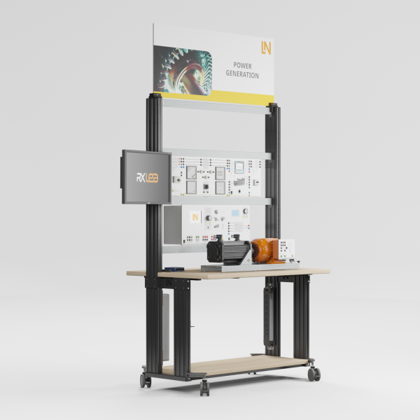
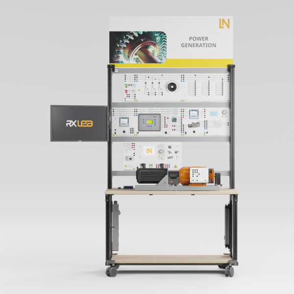
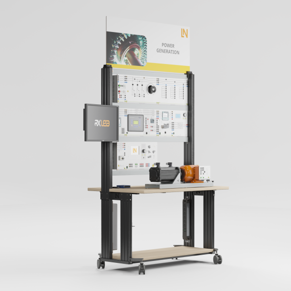
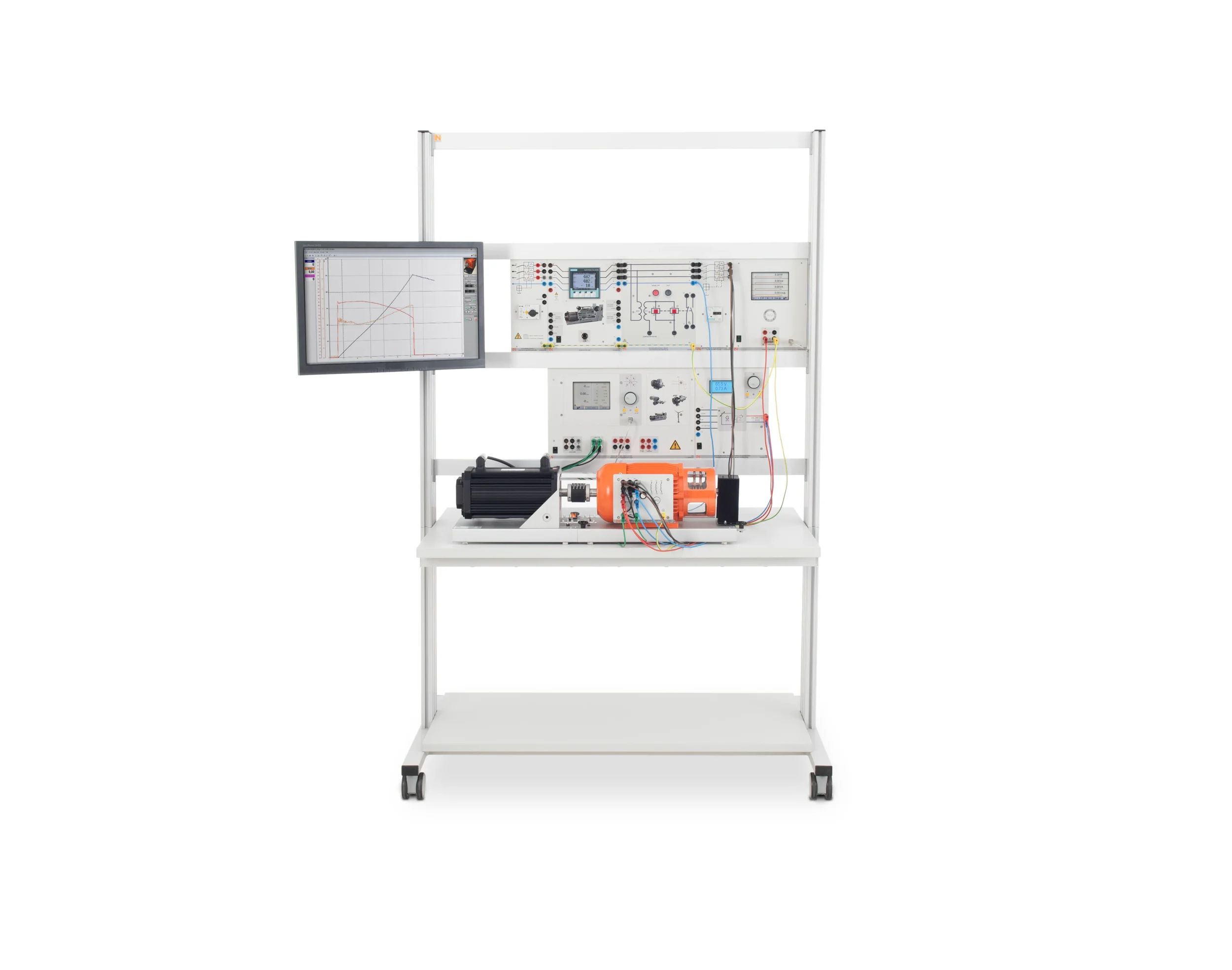
Equipment for rotor ground fault protection: participants investigate the behavior of a synchronous generator in the event of insulation faults in the excitation circuit, connect a rotor ground fault relay and test its function.

Learning Content
  • Comparing fault-free and faulty rotor circuits
  • Performing a relay function test
  • Determining the ground fault current and demonstrating the response
KEY FEATURES
  • Fault emulation in the ungrounded excitation circuit
  • Making the symptomless first fault visible by measurement
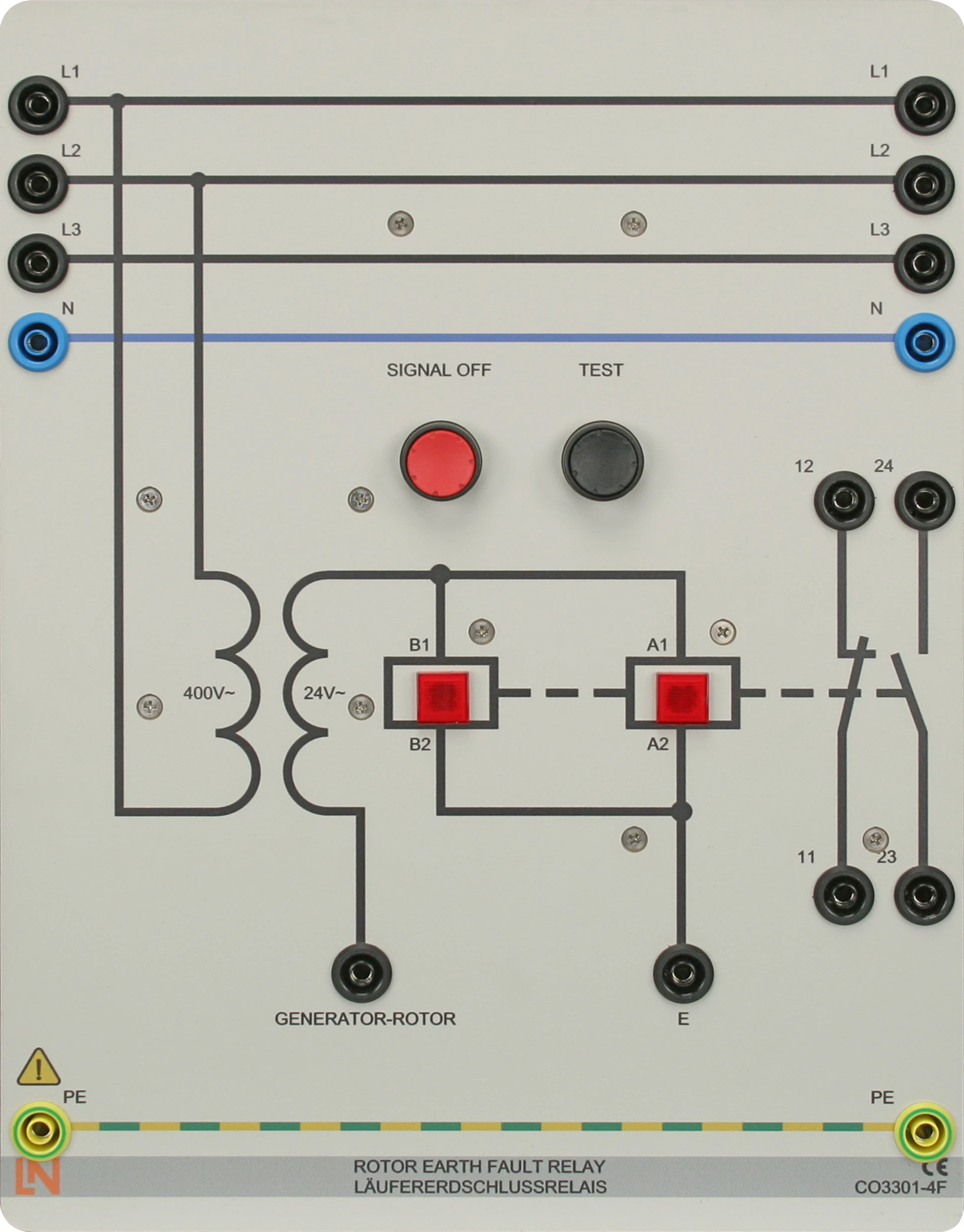
  • Rotor ground fault relay CO3301-4F
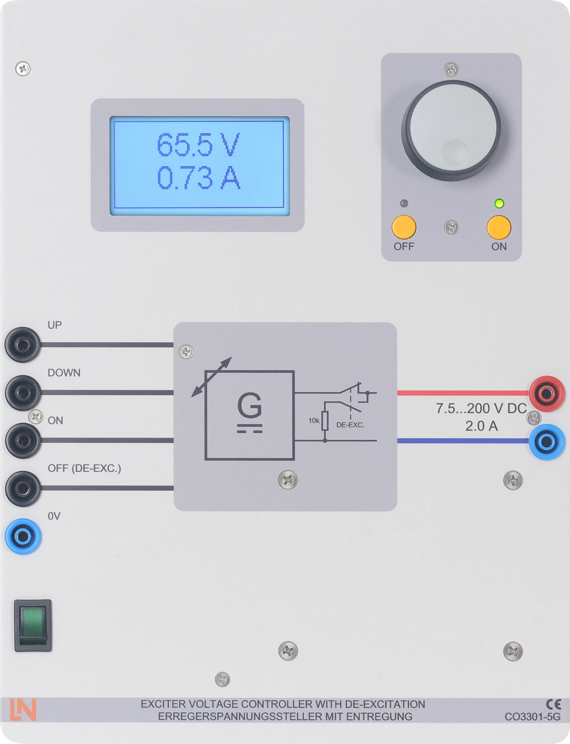
  • Excitation voltage controller CO3301-5G with de-excitation switch
Speak with a Product Specialist +1 (757) 808-5696 · sales@lucas-nuelle.com

A single ground fault in the rotor circuit changes neither the voltage nor the excitation current. Without a protective device it remains invisible, even though it is the precursor to serious damage. This is precisely the condition that the equipment makes measurable. Participants first record the rotor circuit in normal operation and then deliberately apply short circuits to ground at rotor terminals F1 and F2. The rotor ground fault relay CO3301-4F uses a 24 V auxiliary voltage method and signals the fault visually and audibly. Participants determine the ground fault current, test the relay using the test and acknowledge buttons and demonstrate that the protection chain responds. The excitation voltage controller automatically de-excites the machine in the event of a fault.

CO3301-4FRotor-earth fault relay
SO2800-3UInteractive Lab Assistant: Generator protection
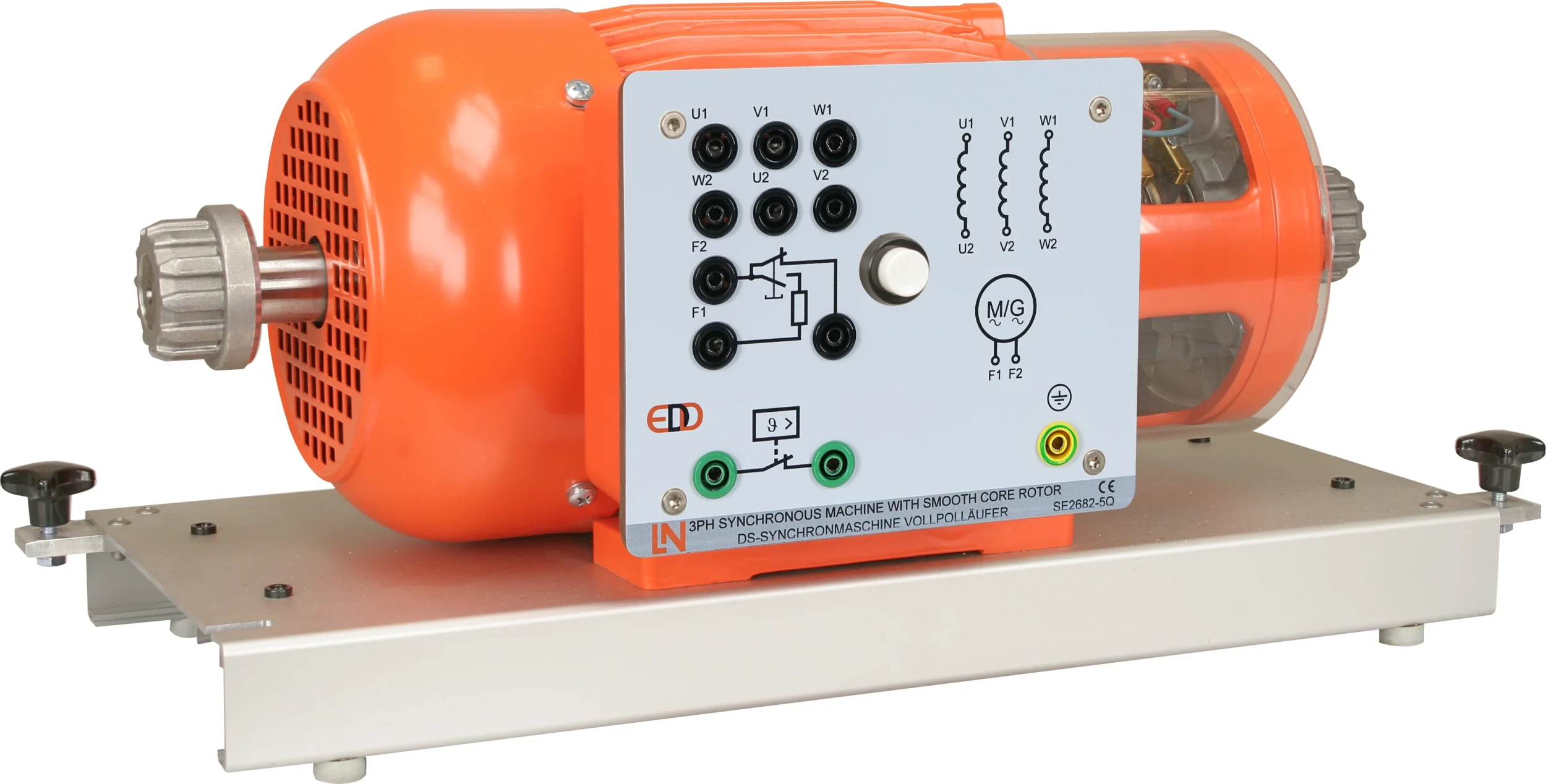
SE2682-5QThree-phase synchronous machine with smooth core rotor, 1kW
CO3301-5GExciter voltage controller with de-excitation
CO3212-1PMotor protection switch, 3 pole, 1.8-2.5A
CO3301-5LHMI (Human Machine Interface) for generators
SO4001-3HSoftware SCADA Viewer
CO3212-5VThree-phase power supply with motor protection switch
CO5127-2APower-Multimeter
LM9057Patch cable Cat5E 1x 1m yellow, 2x 2m yellow
LM8257USB 2.0 Ethernet adapter, 10/100
LM99885-Port Ethernet Switch
ST8010-4JMultiple socket outlet, 6 fold, with illuminated switch
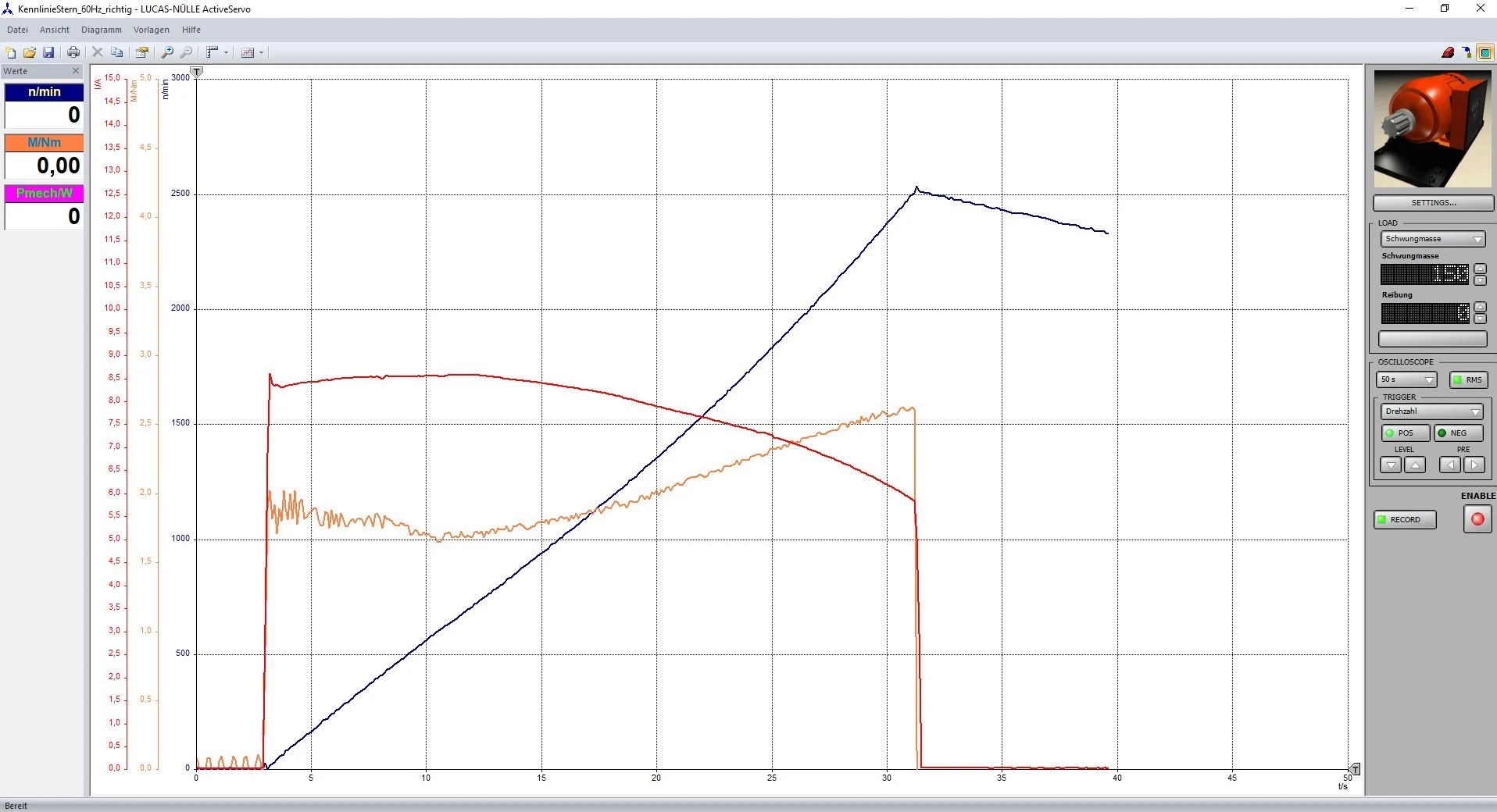
CO3636-6YServo machine test stand for 1kW machines incl. software ActiveServo (D,GB,F,E)
SE2662-7DCoupling guard with LED lighting for 1kW machines
SE2662-6ARubber coupling sleeve, 1kW
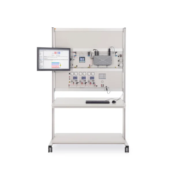
ST7200-7ASybaPro experiment trolley, 3-level, 6 sockets, 1250x1970x800mm
ST8010-4TMonitor holder for flat screen monitor of weight up to 15kg / 33lbs
ST7200-5LProtection cover for three-level experiment trolleys
ST8010-4GKeyboard adapter for flat screen monitor holders
ST8008-8NProtected power distribution for working stations
ST8010-4JMultiple socket outlet, 6 fold, with illuminated switch
ST8000-4JDisplay for Power Generation equipment
SO5126-3RSafety connecting plug 4mm with tap (2x), black, 1000V/32A CAT II
SO5126-3VSafety connecting plug 4mm with tap (2x), blue, 1000V/32A CAT II
SO5126-3WSafety connecting plug 4mm with tap (2x), green/yellow, 1000V/32A CAT II
SO5148-1LSet of safety measurement cables, 4mm (31 leads)

Learning Content in Detail

Participants measure the rotor circuit in the fault-free state, deliberately create ground faults and check the connection and function of the protective relay.

Comparing fault-free and faulty rotor circuits

Participants analyze the generator without a fault and with a single ground fault, and explain why the fault cannot be detected by measurement.

Performing a relay function test

Participants trigger the test using the test and acknowledge buttons and validate the visual and audible signaling devices.

Determining the ground fault current and demonstrating the response

Participants apply short circuits to ground at F1 and F2, measure the ground fault current and demonstrate that the protection components respond.

Features & Applications

The experiments use measurements to record the rotor circuit in normal operation and during deliberately simulated ground faults at rotor terminals F1 and F2.
  • Fault emulation in the ungrounded excitation circuit — Short circuits to ground can be applied safely at different points of the rotor winding, at terminals F1 and F2. Participants determine the resulting ground fault current in each case.
  • Making the symptomless first fault visible by measurement — A single insulation breakdown in the rotor circuit of the rotating synchronous machine does not change the voltage or excitation current. Participants experience that the fault goes unnoticed without a protective device and deduce the benefit of the relay from this.
  • Rotor ground fault relay CO3301-4F — The training panel uses the 24 V auxiliary voltage method, contains a blocking capacitor against direct current and has 10 A switching contacts.
  • Excitation voltage controller CO3301-5G with de-excitation switch — The controller supplies 7.5 to 200 V at a maximum of 2 A and automatically de-excites the generator in the event of a fault.
  • Four-quadrant test bench CO3636-6Y — The test bench operates statically and dynamically in four quadrants and provides ten driven machine models, including a fan, a pump and a time-dependent load.
  • Power multimeter CO5127-2A — The measuring instrument records the electrical variables of the rotor circuit in normal operation and in the event of a fault. Participants use it to determine the ground fault current and document the series of measurements.
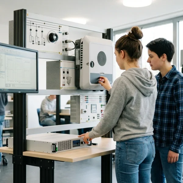
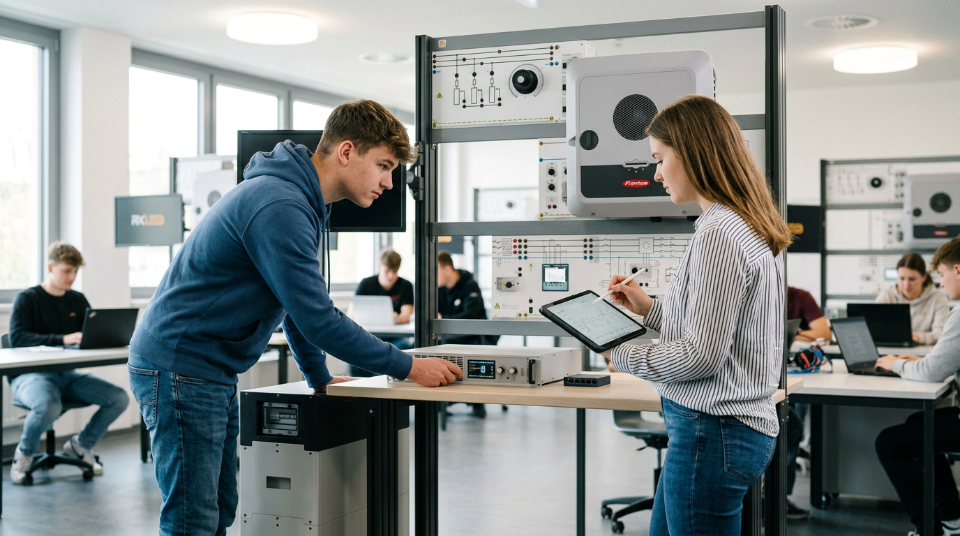
Learners working with RXLea on a tablet at a Lucas-Nuelle training system
RXLea

From Knowledge Comes Capability.

You guide the learning

Where theory and practice go hand in hand.

RXLea brings a new way of learning: project-based, hands-on and clearly structured. Learners solve real-world tasks, while instructors save time on preparation. Interactive modules, smart analytics and real hardware create a modern, efficient learning world.

Hands-on and interactive

Animations, interactive tasks and realistic scenarios build a deep understanding. All content is organized into clear learning paths for focused, hands-on learning.

Digital support

3D assembly animations and digital instructions simplify complex procedures, reduce errors and help learners work more independently.

Visual support

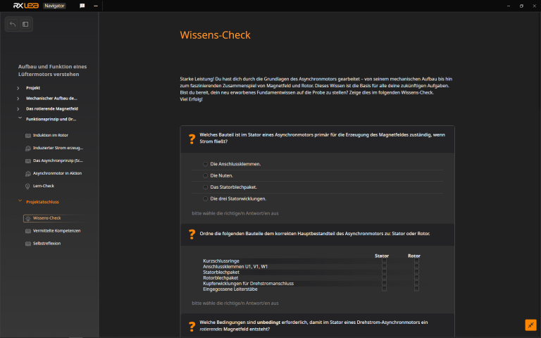
Overview graphics, screenshots and sample animations make the learning world transparent. Photos from the learning packages are also available, including country-specific versions where needed.

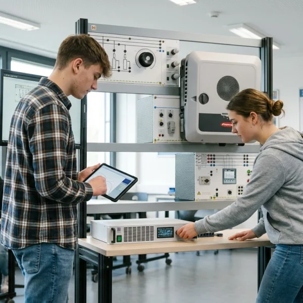
Learners using a tablet at an energy training system
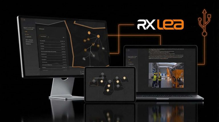
RXLea on desktop, laptop and tablet
RXLea Path Creator for building learning journeys
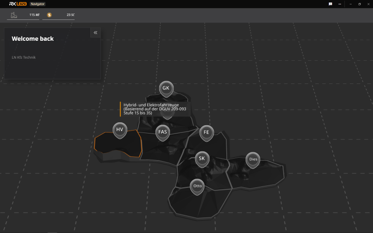
RXLea Navigator showing the learning world
Learn more about RXLea
Newsletter

Stay ahead in
technical training.

Get the latest training systems, product launches and educational insights, delivered directly to your inbox.

Your email address

By subscribing, you agree to our Privacy Policy. You can unsubscribe at any time.

 Please select at least one category before subscribing.
I'm interested in - select all that apply