

Closed-Loop Control of a 4-Quadrant Drive System
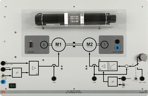
Training system for speed and cascade control on two coupled DC motors. Learners identify the controlled system, design controllers using common tuning rules and test them under defined load steps.
- Carrying out system identification
- Applying tuning rules
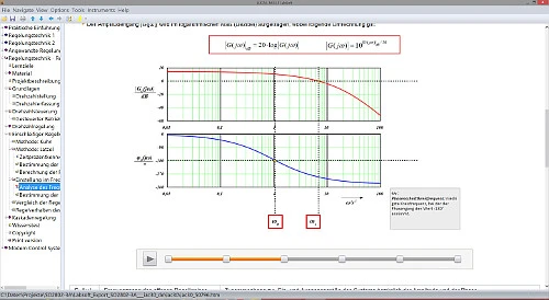
- Analyzing the Bode diagram
- Building a cascade control system
- Four-quadrant control
- Integrated current control
- Integrated measuring and control instruments
- Dynamic load simulation
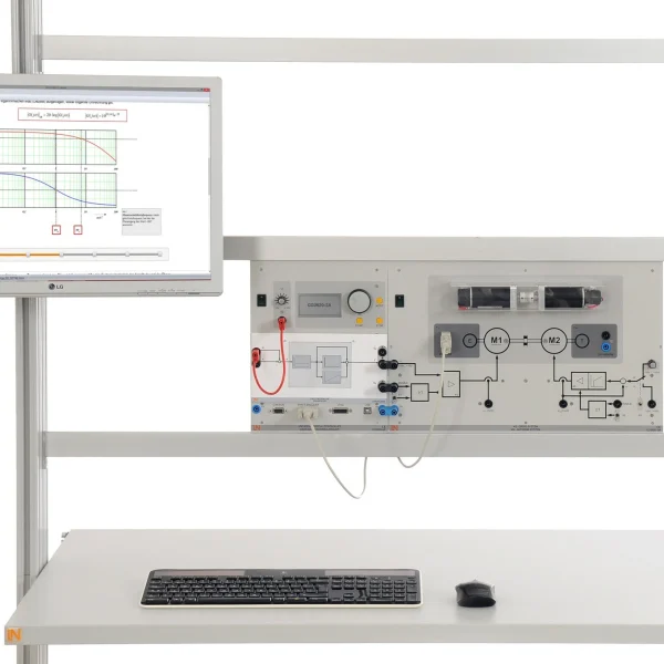
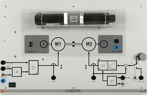
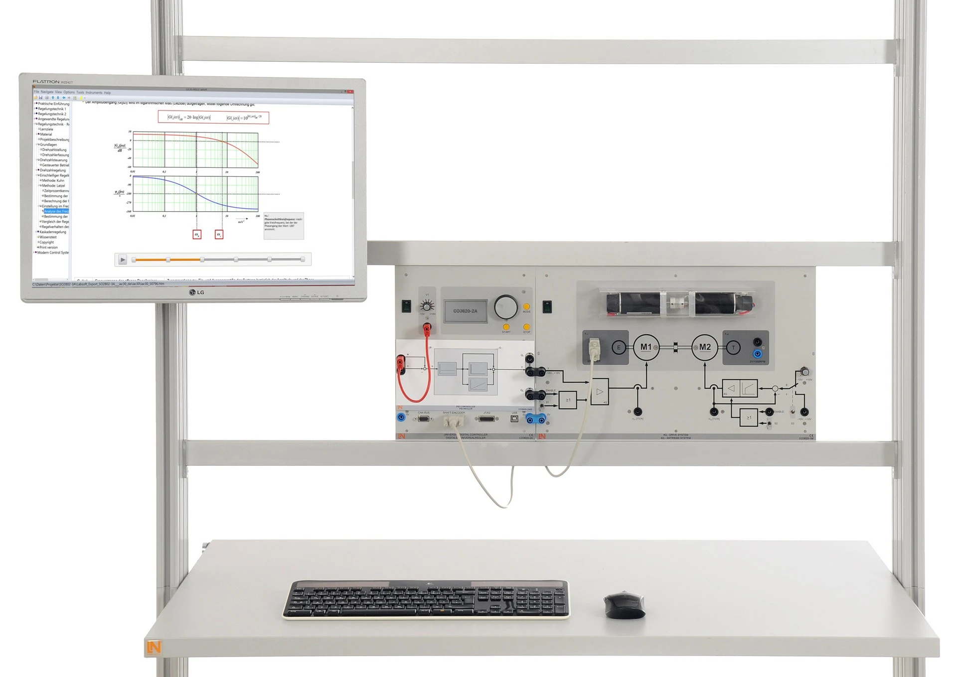
Controlled drives with demanding dynamic requirements are found in machine tools and robot systems. The training system allows their behavior to be investigated in the laboratory: two 90 W motors are mechanically coupled, and two highly dynamic four-quadrant controllers supply up to 6 A. The second motor, with its own current control, acts as a load and generates defined load steps, for example to simulate an elevator ride. A tachogenerator and an incremental encoder measure the speed in analog and digital form. Using the digital universal controller, learners record step responses, determine the system parameters in the time and frequency domain, optimize the controllers using the Kuhn, Latzel and Ziegler–Nichols methods and then build a cascade of current and speed control.
| Base Product | |
| CO3620-1M | Self-commutated converter circuits |
| Course | |
| SO2802-3A | Interactive Lab Assistant: Closed-loop control of a 4-quadrant drive system |
| Accessories | |
| CO3620-2A | Universal digital controller (DSP) |
| Furniture | |
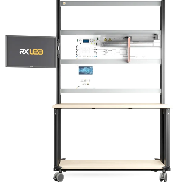
| ST7200-7A | SybaPro experiment trolley, 3-level, 6 sockets, 1250x1970x800mm |
| ST8010-4T | Monitor holder for flat screen monitor of weight up to 15kg / 33lbs |
| ST7200-5L | Protection cover for three-level experiment trolleys |
| ST8010-4G | Keyboard adapter for flat screen monitor holders |
| ST8008-8N | Protected power distribution for working stations |
| ST8010-4J | Multiple socket outlet, 6 fold, with illuminated switch |
| Furniture Accessories | |
| ST8000-6A | Display for the Control Technology equipment |
| Measurement Leads | |
| SO5148-1V | Set of safety measurement cables, 4mm (20 leads) |
| SO5126-3R | Safety connecting plug 4mm with tap (2x), black, 1000V/32A CAT II |
| SO5126-3V | Safety connecting plug 4mm with tap (2x), blue, 1000V/32A CAT II |
Learning Content in Detail
Carrying out system identification
Applying tuning rules
Analyzing the Bode diagram
Building a cascade control system
Investigating load steps
Testing speed measurement
Features & Applications
- Four-quadrant control — Learners analyze the dynamic starting and braking behavior of the motor in both directions of rotation.
- Integrated current control — Internal sensors measure the motor currents directly. Learners use them to parameterize highly dynamic current control loops.
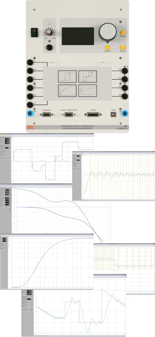
- Integrated measuring and control instruments — Recording step responses, analyzing dynamic behavior and tuning the PID controller: everything takes place directly on the system.
- Dynamic load simulation — Using the coupled second motor, learners simulate load conditions such as an elevator ride and observe how the control system responds.
- 4Q drive system with two 90 W motors — The base unit combines two motors with the power electronics: two highly dynamic four-quadrant controllers with an output current of up to 6 A.
- Tachogenerator and incremental encoder — Two sensors measure the speed, one analog and one digital. Learners compare both methods on the same drive.
- Load motor with integrated current control — Current control on one of the two motors enables defined, reproducible load steps.
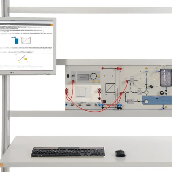
- Digital universal controller (CO3620-2A) — The universal control unit comes with numerous interfaces for typical controlled systems. Its software functions handle real-time analysis and control.
- Step response plotter — Learners record the system’s response to an input step in real time and use it to determine the static and dynamic parameters of the controlled system.
- PID controller — Learners parameterize all controller components interactively and specifically optimize the disturbance and reference response of the connected controlled system.
- Bode plotter — Amplitude and phase response are displayed. Learners use them to carry out frequency response analysis for systematic controller optimization.
- Cascaded PID controller — The instrument is used to set up and optimize cascade control made up of current and speed control.
- System analyzer — The tool compares measured data with models in both the time and the frequency domain, so theory can be applied immediately.

From Knowledge Comes Capability.
You guide the learning
Where theory and practice go hand in hand.
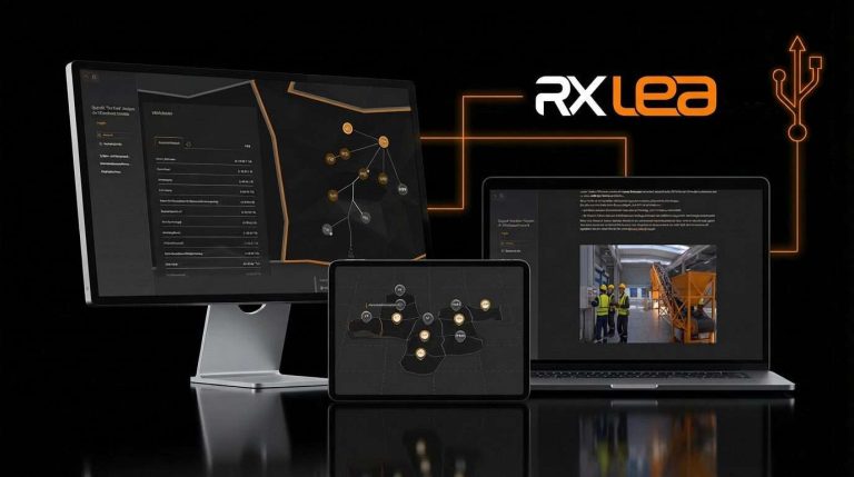
RXLea brings a new way of learning: project-based, hands-on and clearly structured. Learners solve real-world tasks, while instructors save time on preparation. Interactive modules, smart analytics and real hardware create a modern, efficient learning world.
Hands-on and interactive
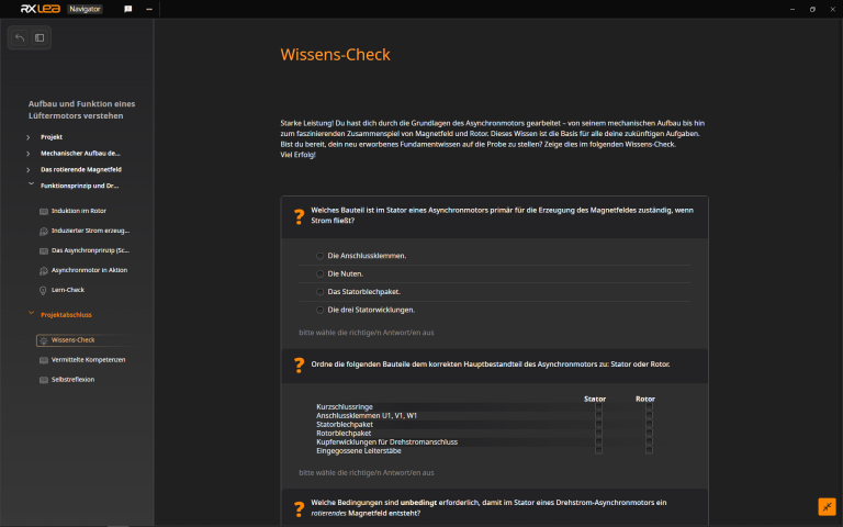
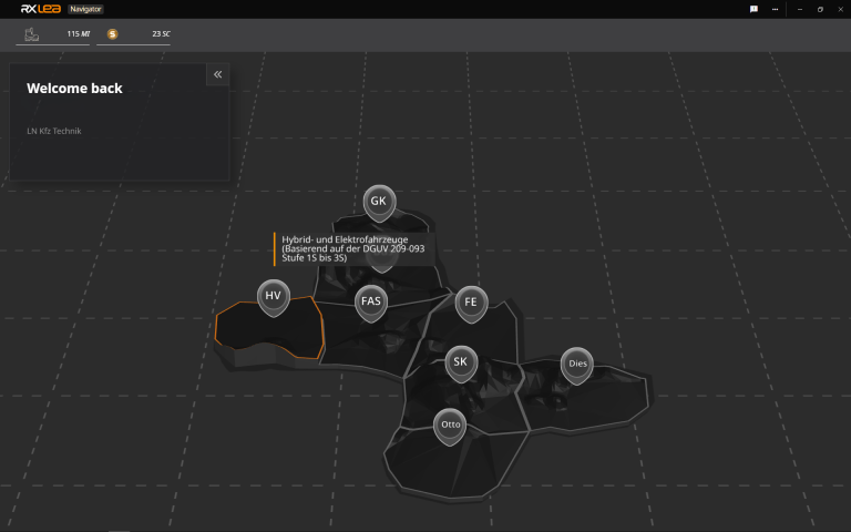
Animations, interactive tasks and realistic scenarios build a deep understanding. All content is organized into clear learning paths for focused, hands-on learning.
Digital support
3D assembly animations and digital instructions simplify complex procedures, reduce errors and help learners work more independently.
Visual support
Overview graphics, screenshots and sample animations make the learning world transparent. Photos from the learning packages are also available, including country-specific versions where needed.

Stay ahead in
technical training.
Get the latest training systems, product launches and educational insights, delivered directly to your inbox.