

Skip to content

Automatically Inspect Assemblies Using Multiple Sensor Technologies

RXLea
Digital projects for hands-on learningInteractive learning content, directly connected to the training system.

Automatically Inspect Assemblies Using Multiple Sensor Technologies

CIU06IU

Teach automated quality inspection through hands-on training. Your students combine different sensor technologies, program assembly inspections, and evaluate results in TIA Portal.

Learning Content
  • Understanding testing processes
  • Comparing sensor principles
  • Programming the target/actual comparison
  • Specifying setpoints on the touchscreen
KEY FEATURES
  • Multi-sensor quality control
  • Integrated PLC for evaluation
  • Displaying test results on the touch panel
  • DC motor with incremental encoder
Speak with a Product Specialist +1 (757) 808-5696 · sales@lucas-nuelle.com

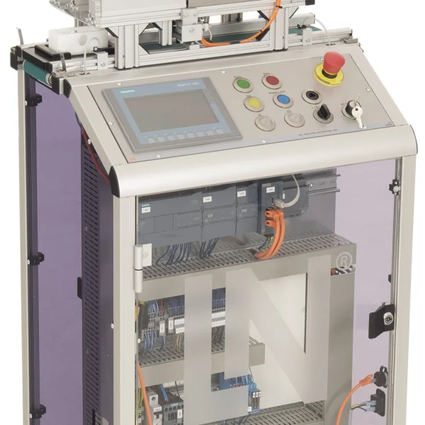
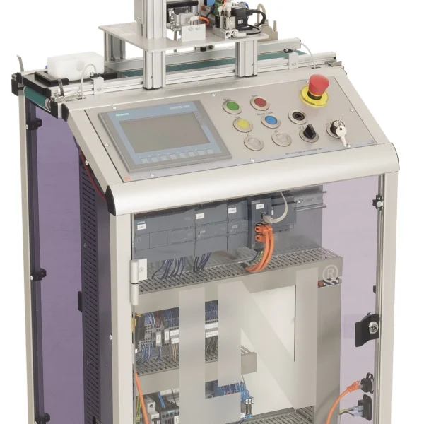
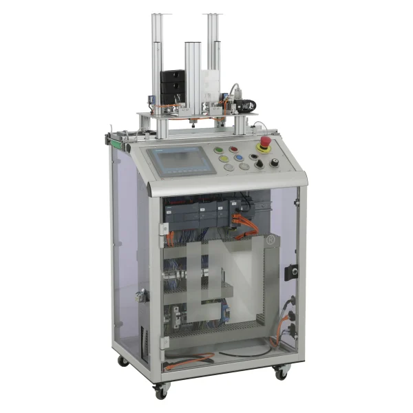
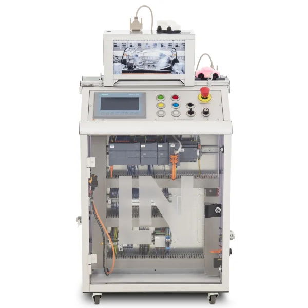
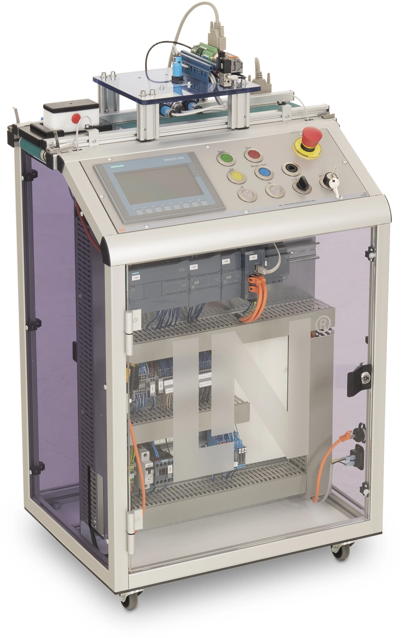
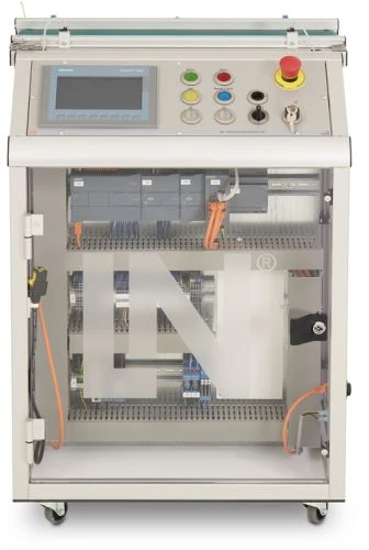
How can assemblies be reliably inspected to verify their correct composition in automated manufacturing processes? The mobile Industrial Mechatronic Unit (IMU) helps you teach your students how different sensor technologies and a programmable logic controller (PLC) work together in industrial quality inspection. Students detect workpiece characteristics, compare them against predefined quality criteria, and visualize inspection results.

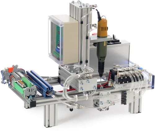
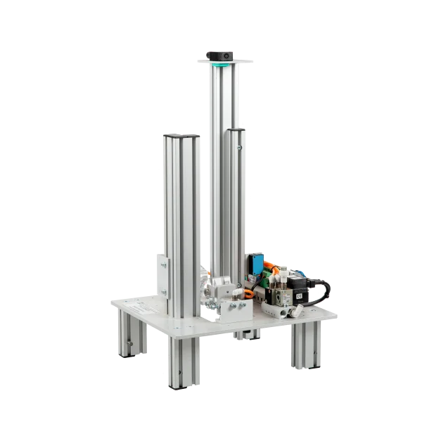
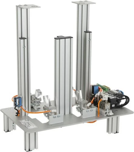
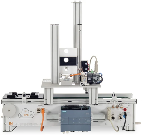
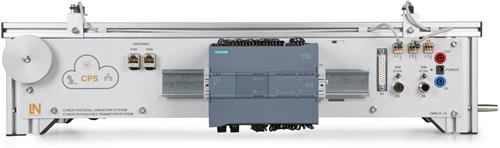
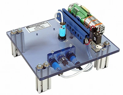
The IMU combines a conveyor system with the inspection subsystem. Two optical sensors detect the colors of the upper and lower housing sections. An inductive sensor distinguishes between metal and nonmetallic connecting pins. A capacitive sensor detects the presence of a workpiece. The integrated Siemens S7-1215C PLC compares the detected sensor signals with predefined product specifications. Inspection results are displayed on the KTP700 touch panel.

Your students develop an automated comparison between actual and target values in TIA Portal and program the evaluation of sensor signals. They design the target value input interface on the touch panel and calibrate the sensors for the respective inspection tasks. Through these activities, they understand the differences between optical, inductive, and capacitive sensing principles and learn when to apply each technology. This helps you build their understanding of industrial quality assurance while developing practical skills in programming, operating, and monitoring automated inspection systems.

LM9536Industrial Mechatronic Unit
LM9532Film, for oscilloscope cameratype LM 7000
SO6200-2UQuickChart, IPA 1 Compact station (GB)
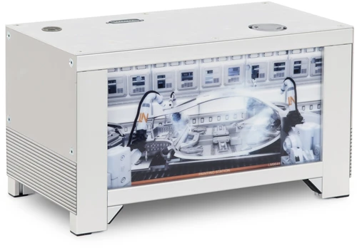
LM9684Testing station
LM9066Interface cable 25-pin, Sub-D socket / plug 1m
SO6200-1FQuickChart, IMS 6 Mechatronics Testing sub-system (GB)
SO2805-5JInteractive Lab Assistant: IMU 1 Industrial Mechatronic Unit
SO2805-5XInteractive Lab Assistant: Self-commutated converter circuits
LM9521Workpiece, top section, white
LM9522Workpiece, top section, black
LM9524Workpiece, bottom section, white
LM9525Workpiece, bottom section, black
LM9527Bolt workpiece, metal
LM9528Bolt workpiece, plastic
LM9521Workpiece, top section, white
LM9527Bolt workpiece, metal
LM9528Bolt workpiece, plastic

Learning Content in Detail

Learners become familiar with the common sensor principles used in quality inspection, program the setpoint/actual comparison and calibrate the sensors on the running station.

Understanding testing processes

Learners analyze how different sensor principles interact in the inspection of subassemblies.

Comparing sensor principles

Learners distinguish between the practical uses of optical, inductive and capacitive sensors.

Programming the target/actual comparison

Learners link measured bit patterns to recipe specifications and use them to identify good and defective parts.

Specifying setpoints on the touchscreen

Learners design HMI screens for entering target colors and pin materials.

Controlling test outputs

Learners set the CHECKED and PASSED signals for further processing in the plant control system.

Controlling speed via PWM

Learners configure the pulse generators of the S7-1200 for smooth positioning at the inspection stopper.

Calibrating sensor thresholds

Learners adjust the optical sensors and check the switching distances of the inductive proximity switches.

Performing fault analysis

Learners identify incorrectly assembled workpieces and signal faults in TIA Portal.

Features & Applications

The unit covers automation technology, quality control and testing technology, and industrial control technology.
  • Multi-sensor quality control — Optical, inductive and capacitive sensors work together to check the material and color of the subassemblies automatically.
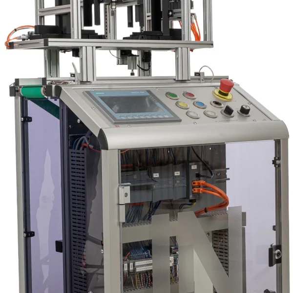
  • Integrated PLC for evaluation — Using the built-in S7-1215, learners control the conveyor belt and the station and evaluate the test results. No external logic unit is required.
  • Displaying test results on the touch panel — The KTP700 touch panel displays pass and fail results graphically and allows the target properties to be specified manually.
  • DC motor with incremental encoder — The drive enables speed-controlled conveyor movements as well as distance and position measurements via pulse evaluation. The belt speed can be adjusted using PWM.
  • Siemens S7-1215C with digital module — The PLC reads in five sensor signals, performs the bit pattern comparison and controls the conveyor belt and stopper.
  • SIMATIC KTP700 Basic Panel (CO3713-4Q) — On the panel, learners specify setpoints for color and material; the panel displays the test result as PASSED or FAILED.
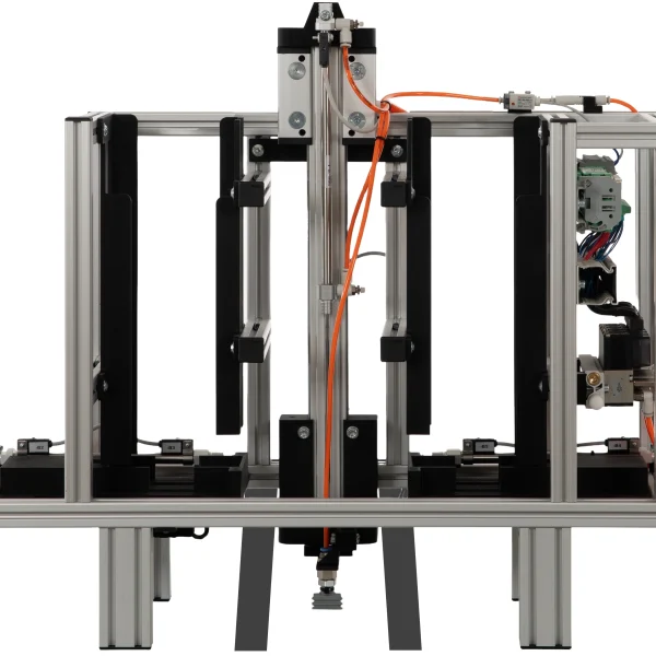
  • Four sensor types for one inspection task — Two optical sensors check whether the top and bottom parts are black or white, an inductive sensor detects the material of the pin and a capacitive sensor checks whether a workpiece is present.
  • Stopper with position feedback — The pneumatic stopper positions the workpiece correctly. A magnetic sensor reports back the position of the stopper.
  • IO-Link with RFID read/write head — An RFID read/write head connected via the IO-Link master module writes data to the workpiece carrier and reads data from it.
  • 25-pin transfer module (-X1) — The module transmits the five sensor signals and the actuator signal of the inspection station to the PLC with reverse polarity protection and supplies the station with power.
  • Siemens TIA Portal and WinCC — Engineering software for bit comparisons, step sequences and the touch panel displays.
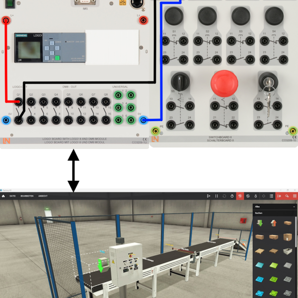
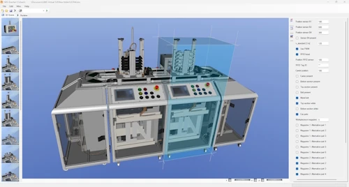
  • Interactive Lab Assistant course SO2805-5J — Interactive learning software with experiment instructions, 3D models and automated knowledge tests.
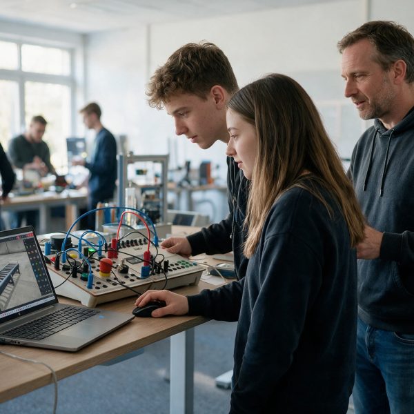
Learners working with RXLea on a tablet at a Lucas-Nuelle training system
RXLea

From Knowledge Comes Capability.

You guide the learning

Where theory and practice go hand in hand.

RXLea brings a new way of learning: project-based, hands-on and clearly structured. Learners solve real-world tasks, while instructors save time on preparation. Interactive modules, smart analytics and real hardware create a modern, efficient learning world.

Hands-on and interactive

Animations, interactive tasks and realistic scenarios build a deep understanding. All content is organized into clear learning paths for focused, hands-on learning.

Digital support

3D assembly animations and digital instructions simplify complex procedures, reduce errors and help learners work more independently.

Visual support

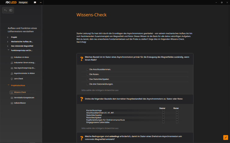
Overview graphics, screenshots and sample animations make the learning world transparent. Photos from the learning packages are also available, including country-specific versions where needed.

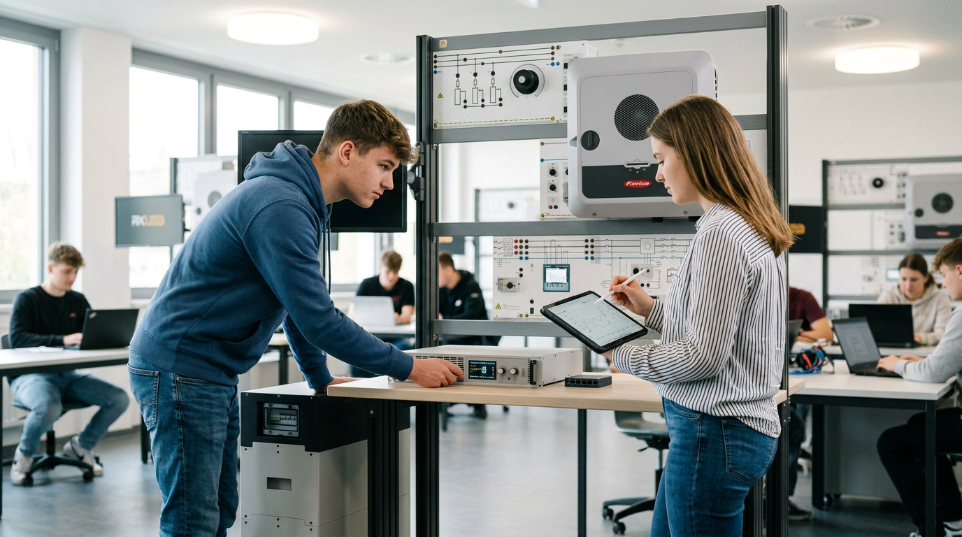
Learners using a tablet at an energy training system
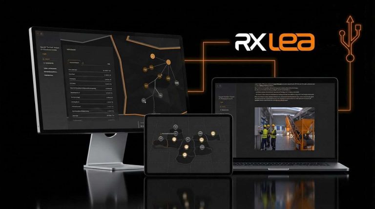
RXLea on desktop, laptop and tablet
RXLea Path Creator for building learning journeys
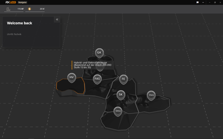
RXLea Navigator showing the learning world
Learn more about RXLea
Newsletter

Stay ahead in
technical training.

Get the latest training systems, product launches and educational insights, delivered directly to your inbox.

Your email address

By subscribing, you agree to our Privacy Policy. You can unsubscribe at any time.

 Please select at least one category before subscribing.
I'm interested in - select all that apply