

Pulse Modulation Methods PWM, PPM
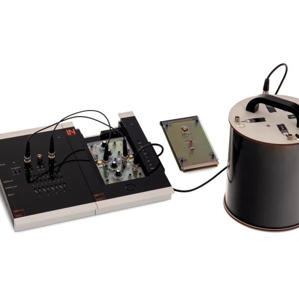
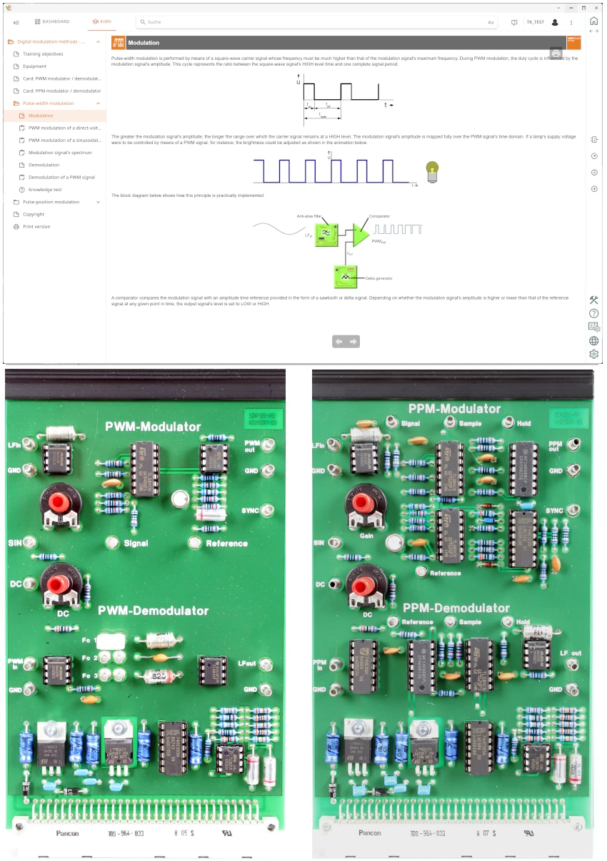
UniTrain course on PWM and PPM: students generate both signal forms on experiment cards, measure the influence of the demodulator filter frequency and compare noise immunity and bandwidth requirements.
- Investigating how PWM works
- Evaluating PWM demodulation
- Analyzing the PWM spectrum
- Analyzing PPM generation
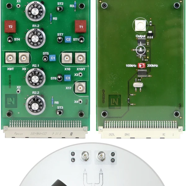
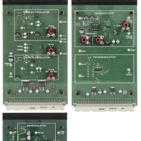
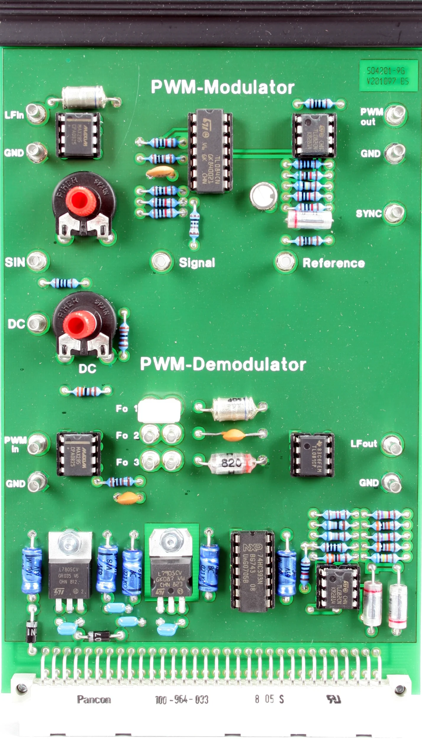
- PWM Modulator and Demodulator experiment card
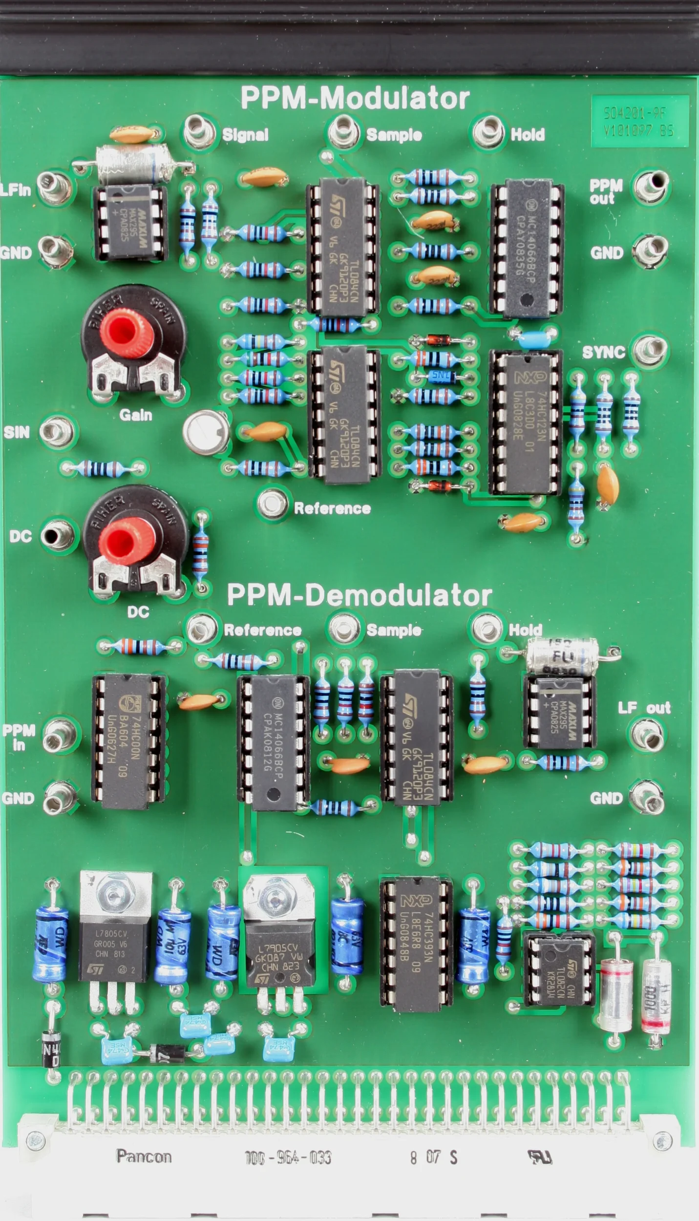
- PPM Modulator and Demodulator experiment card
- Access to internal signals
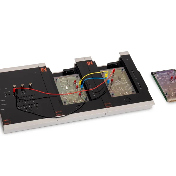
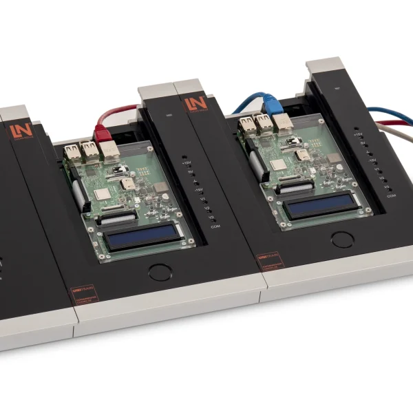
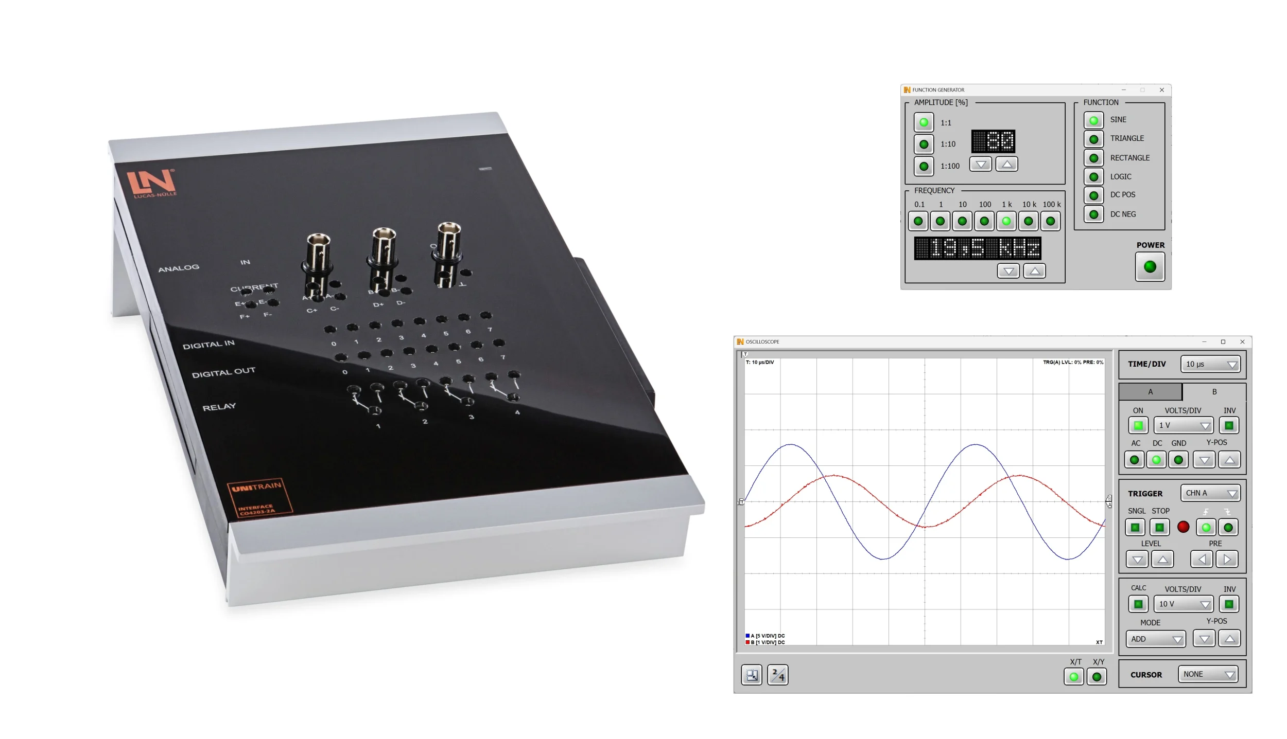
- UniTrain interface
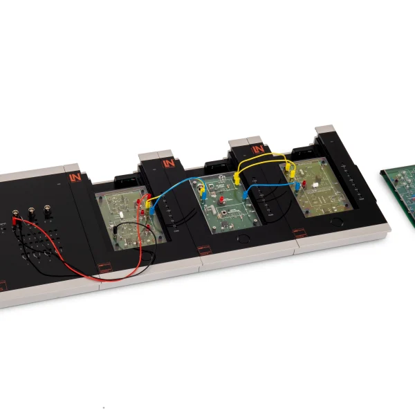
PWM and PPM control power stages, transmit measured values and encode signals in communications engineering. This UniTrain course demonstrates both methods on the circuit. Students feed DC and AC voltages into the PWM modulator, observe the change in pulse width and vary the filter frequency of the demodulator until they can see its effect on the output signal on the oscilloscope and in the spectrum analyzer. On the PPM modulator, they measure the shift of the pulses and tap the internal intermediate stages of the demodulator via 2 mm jacks, so that the demodulation process can be followed step by step. Finally, they compare both methods in terms of noise immunity, bandwidth requirements and circuit complexity.
| Course | |
| CO4204-9K | Course Telecommunications 6: Pulse modulation methods PTM |
| Accessories | |
| CO4203-2A | UniTrain Interface mit virtuellen Instrumenten (Basis VI) |
| CO4203-2J | UniTrain measurement accessories, shunts and connection cables |
| CO4203-2Y | UniTrain storage case for one UniTrain system |
| CO4203-2B | UniTrain Experimenter |
Learning Content in Detail
Investigating how PWM works
Evaluating PWM demodulation
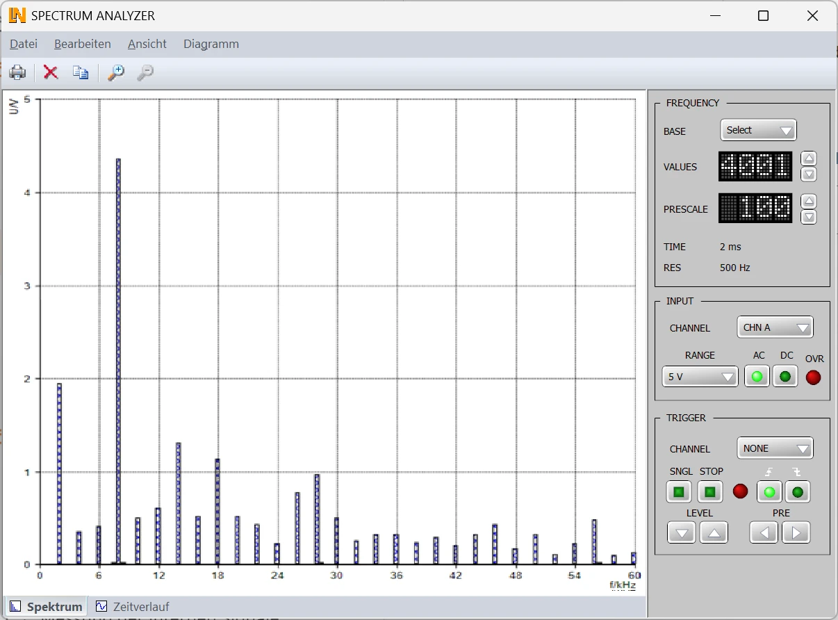
Analyzing the PWM spectrum
Students investigate the frequency spectrum of the PWM signal with the spectrum analyzer and evaluate how well PWM is suited to signal transmission.
Analyzing PPM generation
Measuring internal demodulator signals
Comparing modulation methods
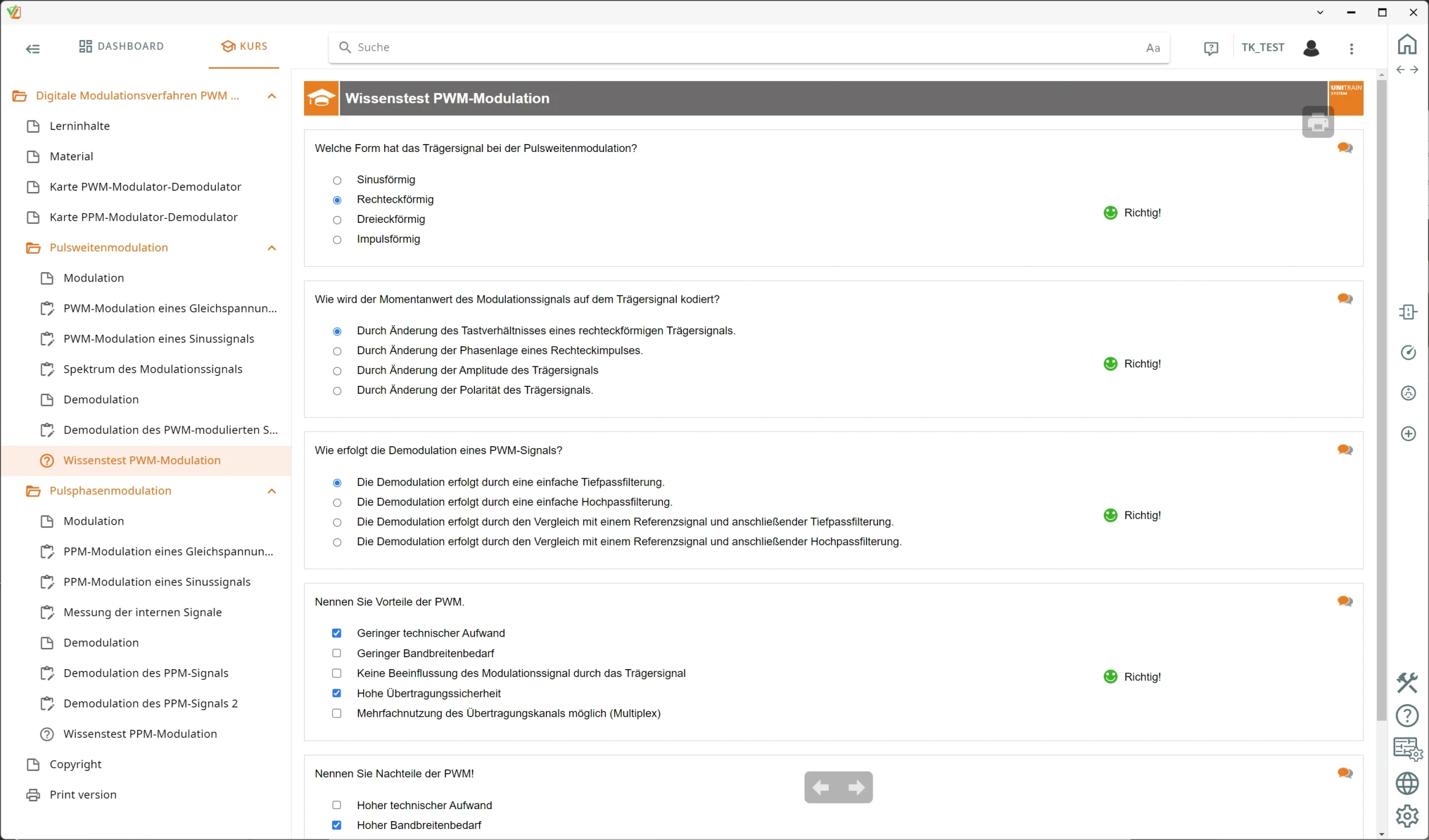
Listing the advantages and disadvantages of PWM
Features & Applications
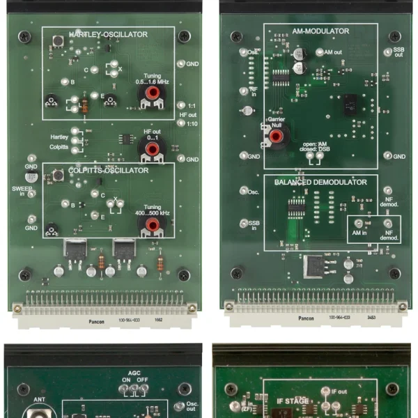
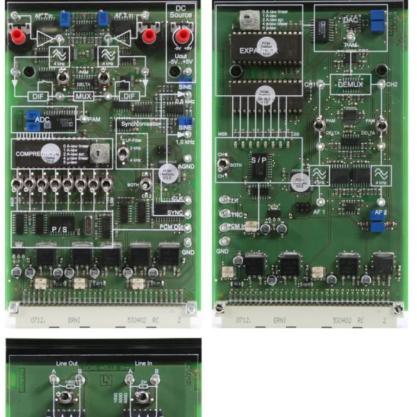
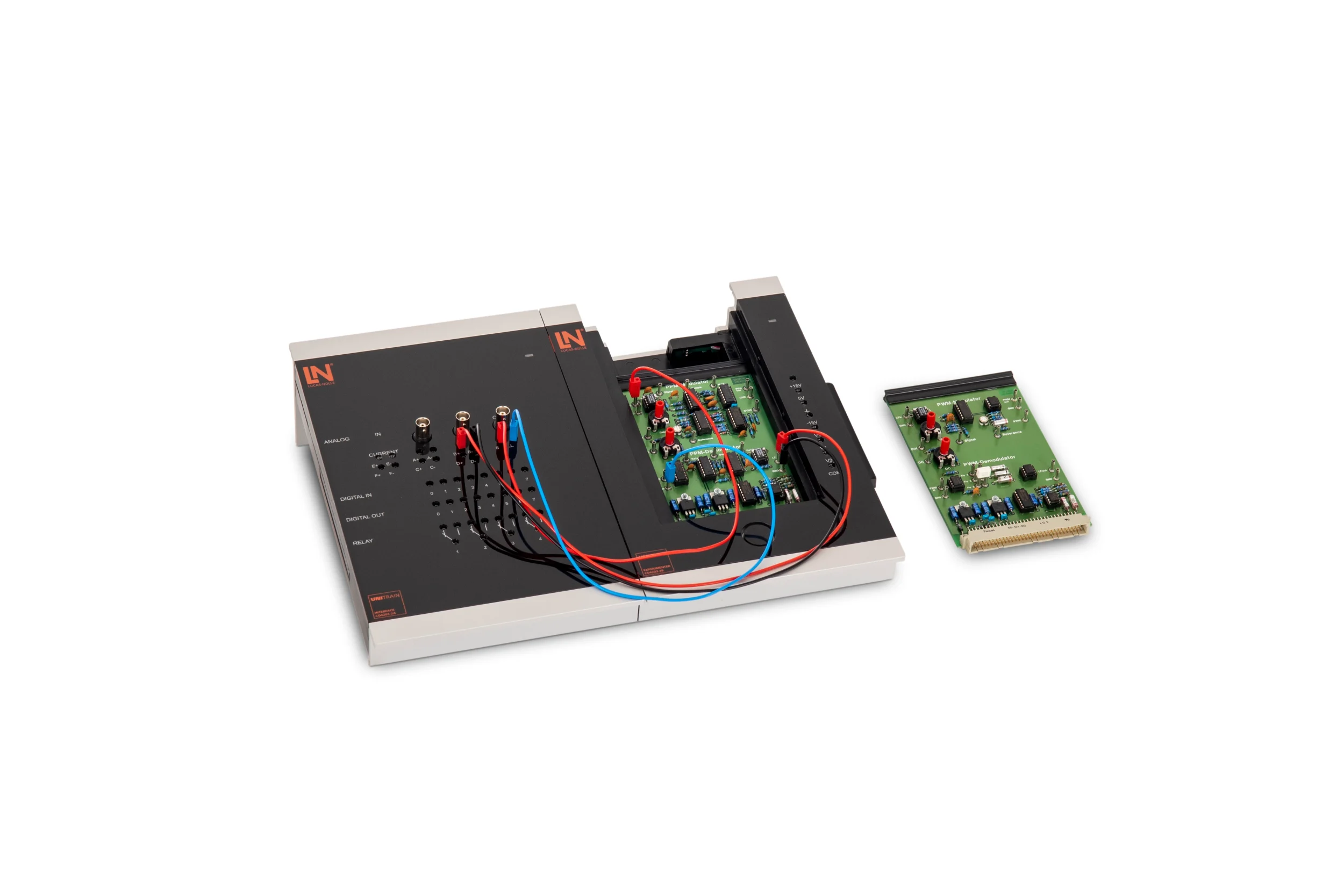
- PWM Modulator and Demodulator experiment card — Generates PWM signals from analog DC and AC voltages and reconstructs them via a demodulator with a tunable filter stage.
- PPM Modulator and Demodulator experiment card — Generates PPM signals from analog DC and AC voltages and provides the reconstructed signals at the output of the demodulator.
- Access to internal signals — The PPM demodulator routes its internal circuit signals to 2 mm jacks, so that the demodulation process can be followed stage by stage on the oscilloscope.
- UniTrain interface — Provides supply voltages as well as analog and digital inputs and outputs. The measurements are controlled via the instruments in LabSoft.
- 2/4-channel oscilloscope — Displays pulse widths, pulse positions and input and output signals in real time and offers cursor functions for measuring the signals.
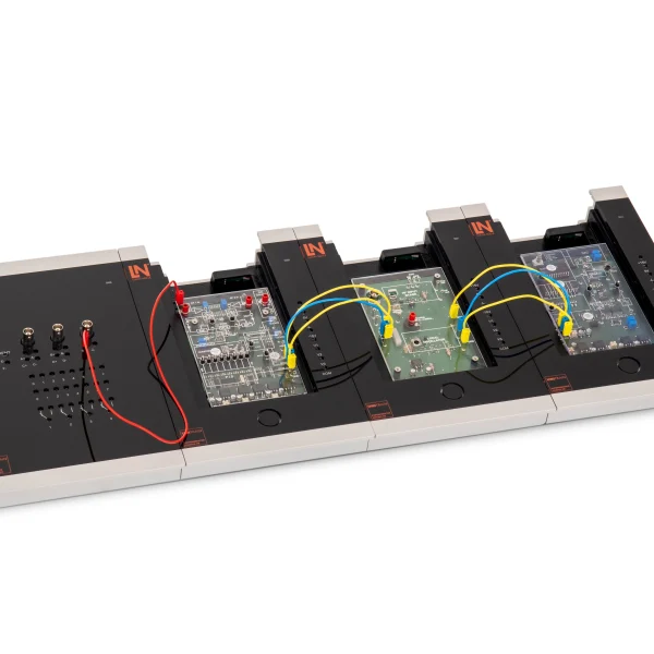
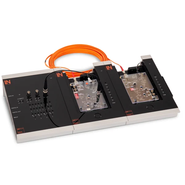
- UniTrain Experimenter — The card holder accommodates the experiment cards and connects them to the UniTrain bus. Cards can be changed quickly, keeping changeover times short.
- Spectrum analyzer — Analyzes the frequency spectrum of sampled signals and makes aliasing effects and the bandwidth requirements of PWM visible.
- LabSoft experiment platform — Guides students through the course, provides the instruments for controlling the UniTrain interface and documents learning progress.
- Analyzing pulse width modulation and demodulation — Students investigate how PWM signals are generated and measure the influence of the filter bandwidth on the quality of the demodulated output signal.
- Trying out pulse position modulation and signal stages — Students measure the signal waveforms at the modulator and demodulator with the oscilloscope and tap internal intermediate stages of the PPM circuit via 2 mm jacks.
- Varying the filter frequency — Students adjust the filter frequency of the demodulator manually and follow the harmonic filtering in the spectrum analyzer and on the oscilloscope.
- Comparing and evaluating modulation methods — Students compare PWM and PPM in terms of noise immunity, bandwidth requirements and circuit complexity and justify which method is suitable for which purpose.

From Knowledge Comes Capability.
You guide the learning
Where theory and practice go hand in hand.
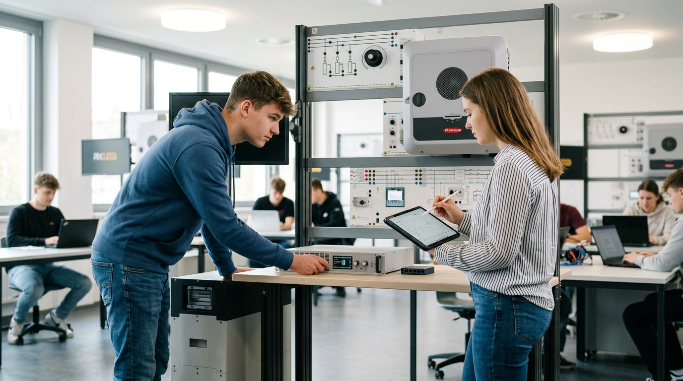
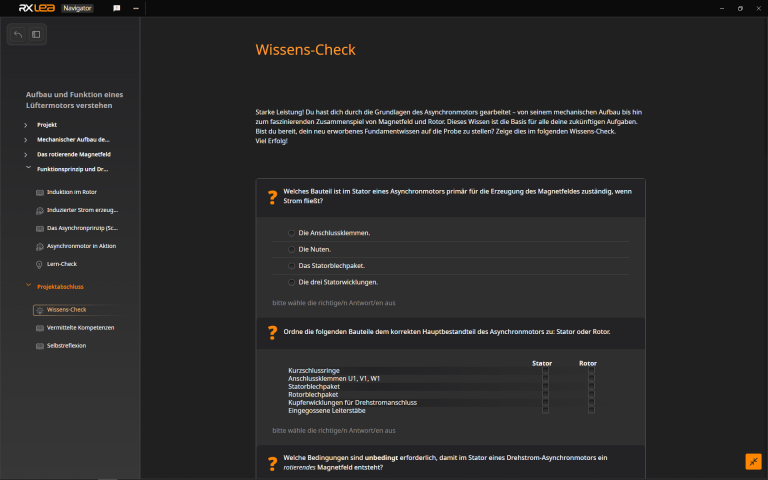
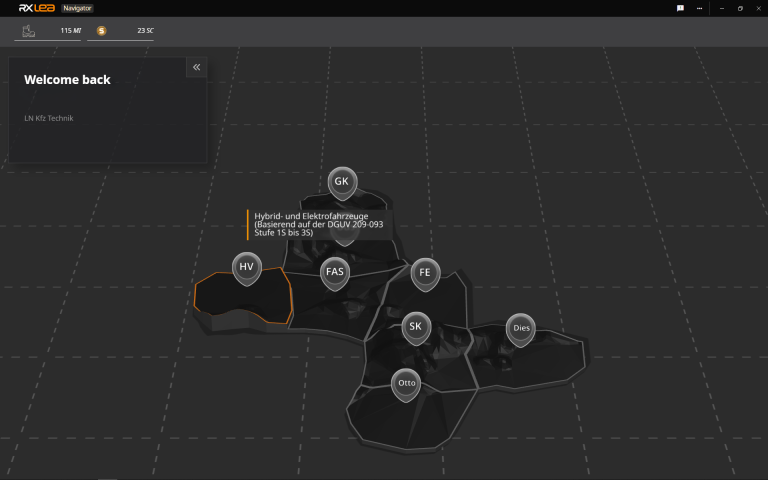
RXLea brings a new way of learning: project-based, hands-on and clearly structured. Learners solve real-world tasks, while instructors save time on preparation. Interactive modules, smart analytics and real hardware create a modern, efficient learning world.
Hands-on and interactive
Animations, interactive tasks and realistic scenarios build a deep understanding. All content is organized into clear learning paths for focused, hands-on learning.
Digital support
3D assembly animations and digital instructions simplify complex procedures, reduce errors and help learners work more independently.
Visual support
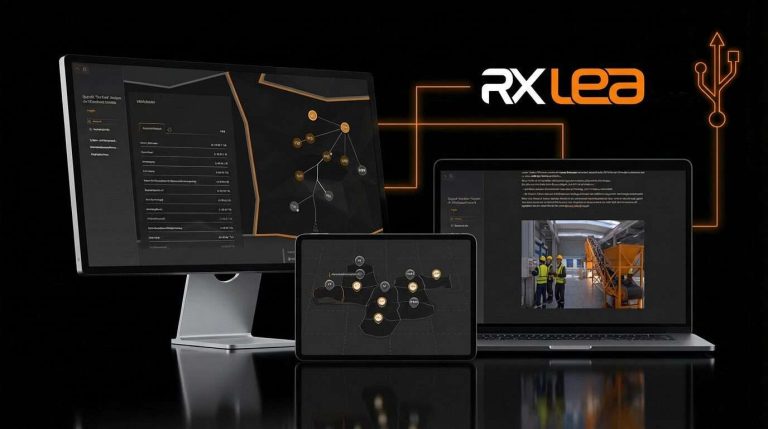
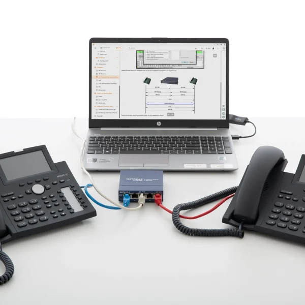
Overview graphics, screenshots and sample animations make the learning world transparent. Photos from the learning packages are also available, including country-specific versions where needed.

Stay ahead in
technical training.
Get the latest training systems, product launches and educational insights, delivered directly to your inbox.