

Skip to content

Optical Fibers for Wavelengths 650 nm / 820 nm

RXLea
Digital projects for hands-on learningInteractive learning content, directly connected to the training system.

Optical Fibers for Wavelengths 650 nm / 820 nm

TLW01UT

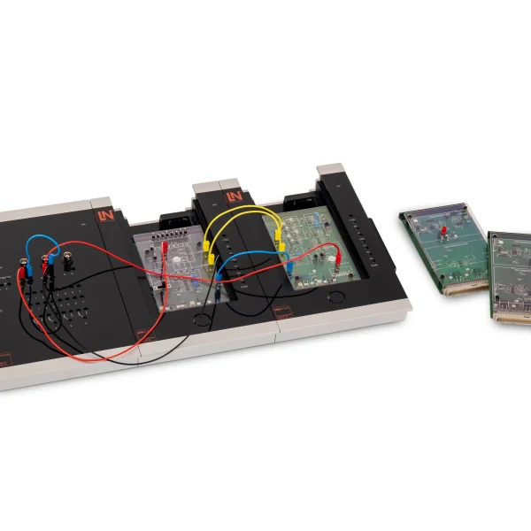
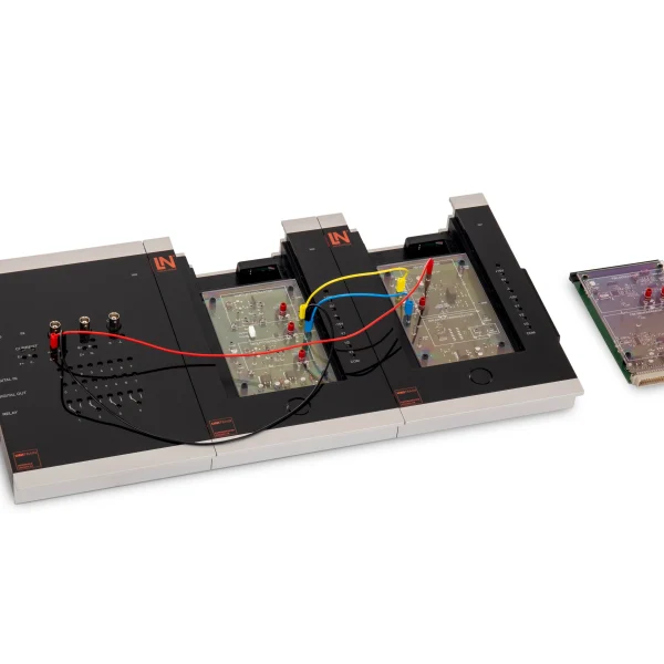
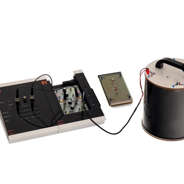
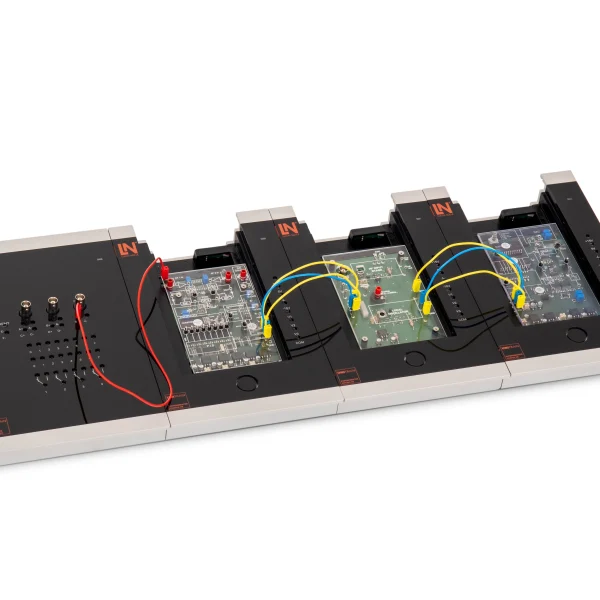
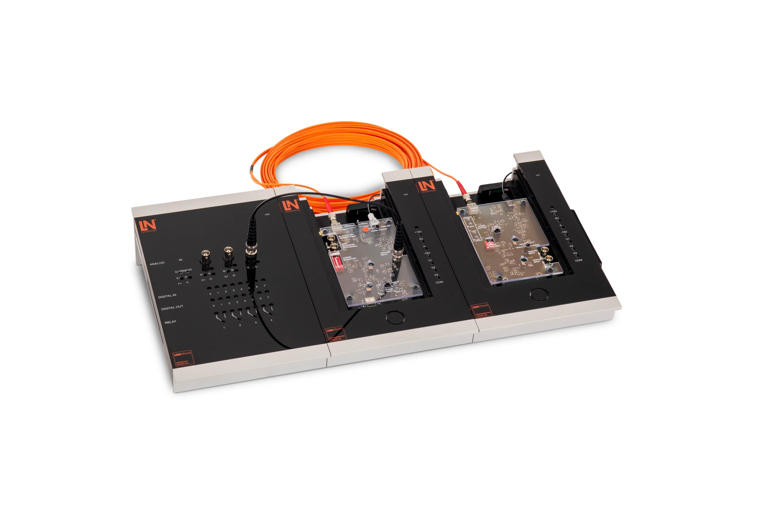
UniTrain training system for optical transmission: students build fiber-optic links with plastic and glass fiber, measure attenuation and dispersion and assemble connectors.

Learning Content
  • Investigating optical transmission properties
  • Comparing fiber types
  • Applying connection technology
  • Assembling and measuring connectors
KEY FEATURES
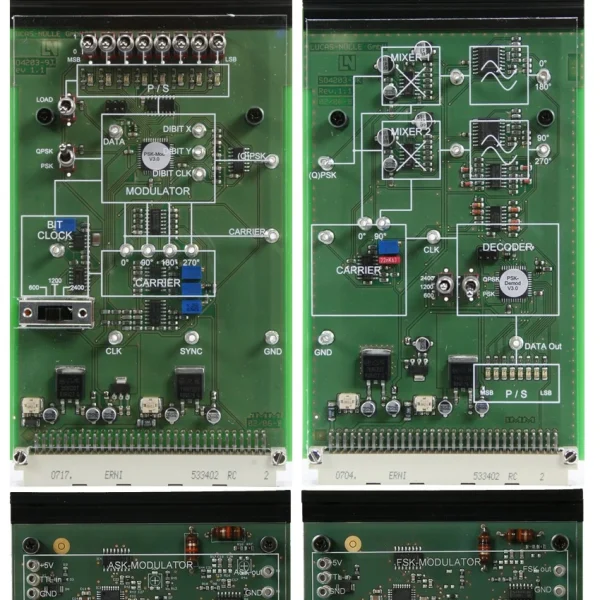
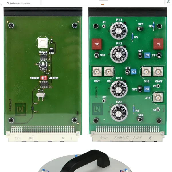
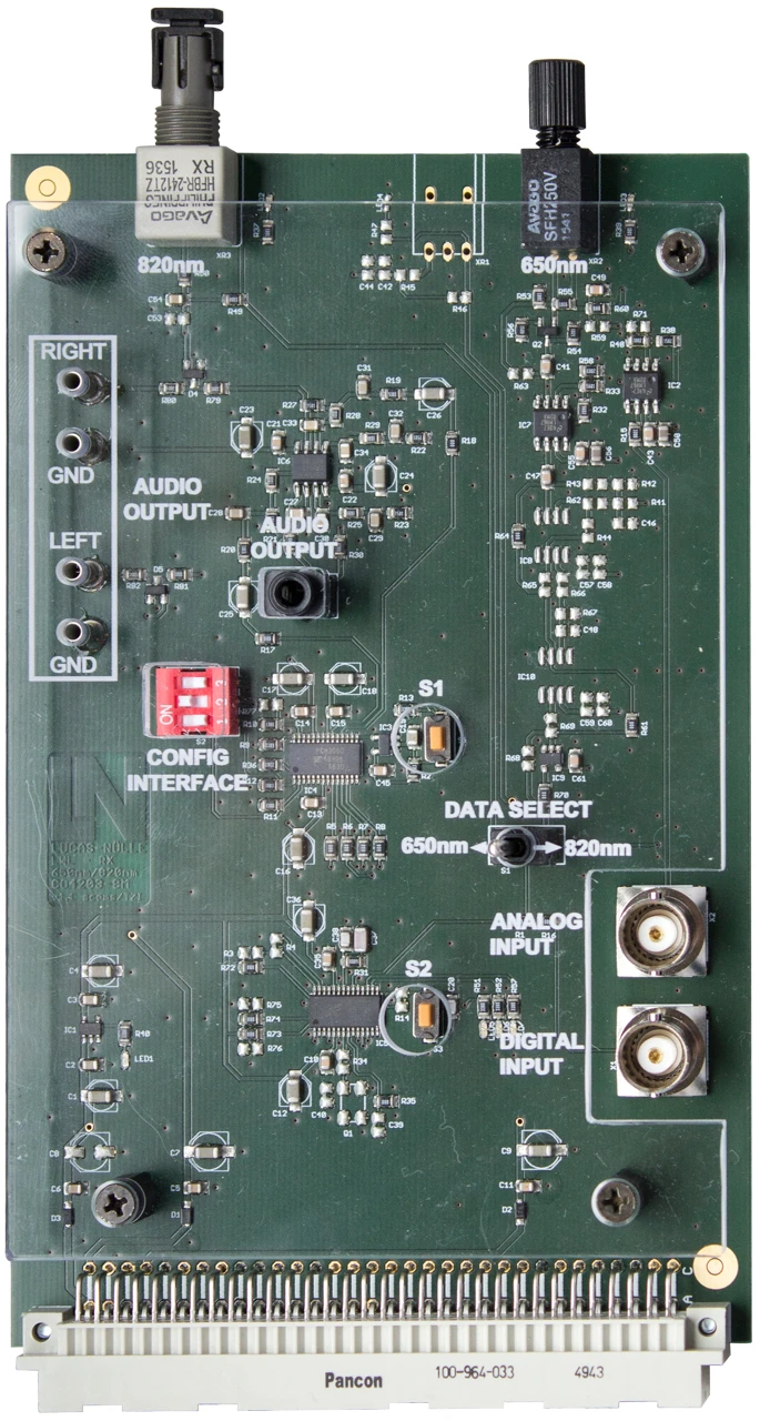
  • Fiber-Optic Receiver 650 nm / 820 nm experiment card
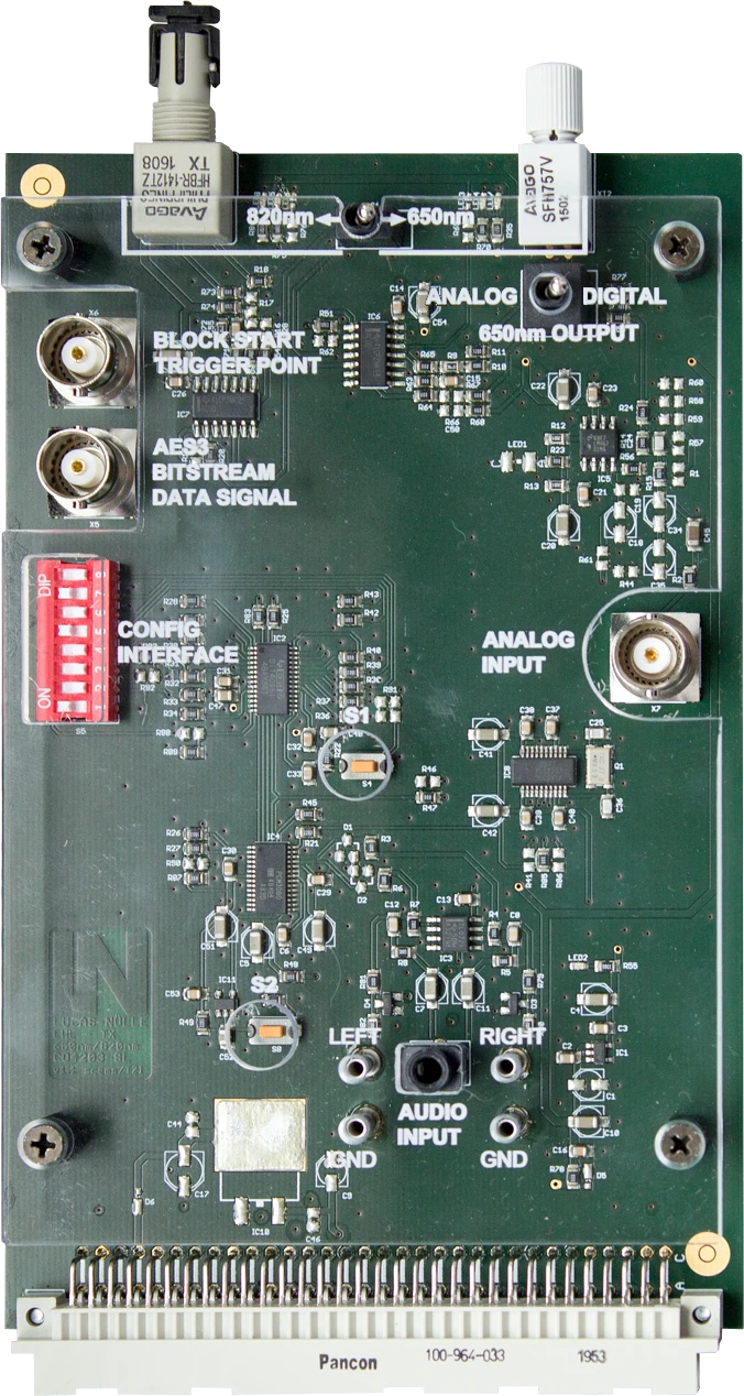
  • Fiber-Optic Transmitter 650 nm / 820 nm experiment card
  • Analyzing optical transmission media
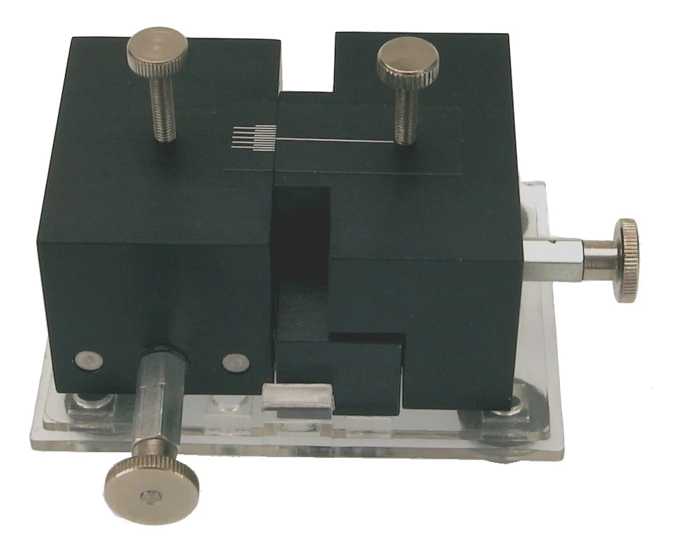
  • Optical gauge for splice analysis
Speak with a Product Specialist +1 (757) 808-5696 · sales@lucas-nuelle.com

Optical transmission links carry high bandwidths and are extremely difficult to tap. How well a link performs depends on the fiber, the coupling and the connector. This UniTrain training system lets students build the link themselves: the transmitter and receiver cards are switched via DIP switches to 650 nm for plastic optical fiber or 820 nm for multimode glass fiber, and the fiber couples directly onto the card. Students measure attenuation, numerical aperture and dispersion, transmit analog audio signals and digital bit streams and compare the signal quality of the two fiber types. They prepare fibers with special tools, clean the end faces, make plug-in connections and measure their insertion loss.

CO4205-4ECourse: Optical fibres for wavelengths 650 nm / 820 nm
CO4203-2AUniTrain Interface mit virtuellen Instrumenten (Basis VI)
CO4203-2JUniTrain measurement accessories, shunts and connection cables
CO4203-2YUniTrain storage case for one UniTrain system
CO4203-2BUniTrain Experimenter

Learning Content in Detail

Students work their way from the physical properties of the fiber to a fully assembled and measured transmission link.

Investigating optical transmission properties

Students determine attenuation, numerical aperture and dispersion by calculation and by measurement.

Comparing fiber types

Students distinguish between multimode and single-mode fibers in terms of mode propagation and bandwidth limitation.

Applying connection technology

Students assemble detachable connectors, clean fiber end faces and assess the insertion loss.

Assembling and measuring connectors

Students terminate optical fibers, clean the end faces and measure the insertion loss of the interface.

Transmitting analog and digital signals

Students feed audio signals and PCM bit streams into the optical transmitters and assess the signal quality at the receiver.

Trying out PCM coding

Students investigate the encoding and decoding of pulse code modulation on optical links.

Determining the bandwidth of the link

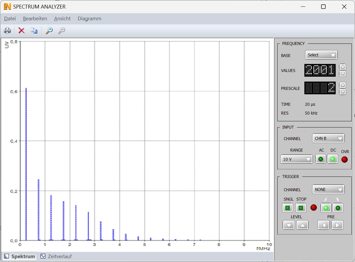
Students compare the spectra of the input and output signals and use them to estimate the bandwidth.

Features & Applications

The experiments address questions from optical communications engineering and fiber-optic networks, as well as from telecommunications and broadband infrastructure.
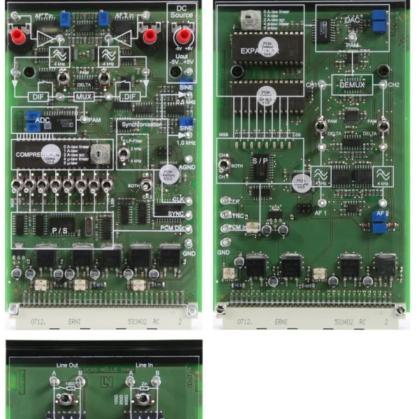
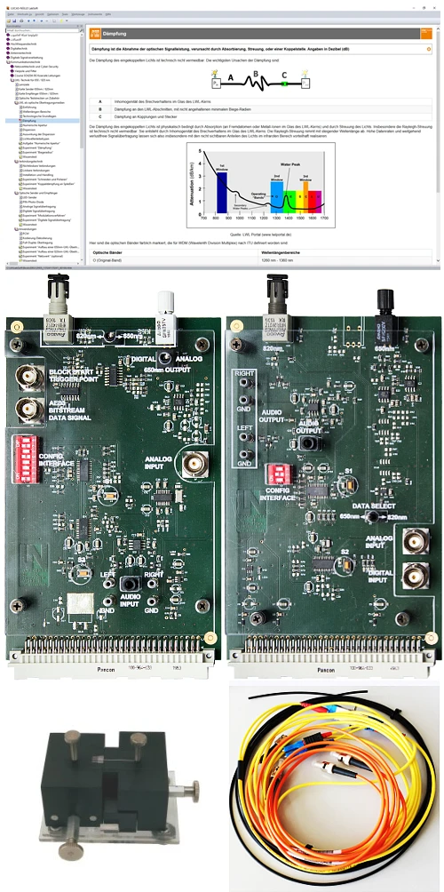
  • Fiber-Optic Receiver 650 nm / 820 nm experiment card — Contains switchable receiver modules for POF and ST connectors, an adjustable receiver amplifier and demodulation circuits for analog and digital signals.
  • Fiber-Optic Transmitter 650 nm / 820 nm experiment card — Contains switchable transmitter modules for plastic fiber at 650 nm and multimode glass fiber with ST connectors at 820 nm, as well as BNC inputs for analog and digital modulation signals.
  • Analyzing optical transmission media — Students investigate physical parameters and wavelength ranges as well as attenuation and dispersion in multimode and single-mode optical fibers.
  • Optical gauge for splice analysis — Students investigate the coupling loss at splice joints with lateral and axial offset under real alignment conditions.
  • Investigating analog and digital signal transmission — Students transmit analog audio signals and digital bit streams over the fiber, investigate the modulation methods and analyze the resulting signal distortion.
  • Modular design with switchable transmission channels — The transmit and receive channels are switched via DIP switches. The fiber couples directly onto the experiment card, and the link can be tested immediately.
  • Plastic and glass fiber compared — Students build links with POF at 650 nm and with OM2 glass fiber at 820 nm and compare the quality of digital audio signals at the output.
  • UniTrain interface — Supplies the transmitter and receiver cards via the UniTrain bus and provides four fast measurement channels, each with a sampling rate of 100 MSample/s.
  • Spectrum analyzer — Students compare the frequency spectrum before and after transmission over the fiber and use it to estimate the bandwidth of the link.
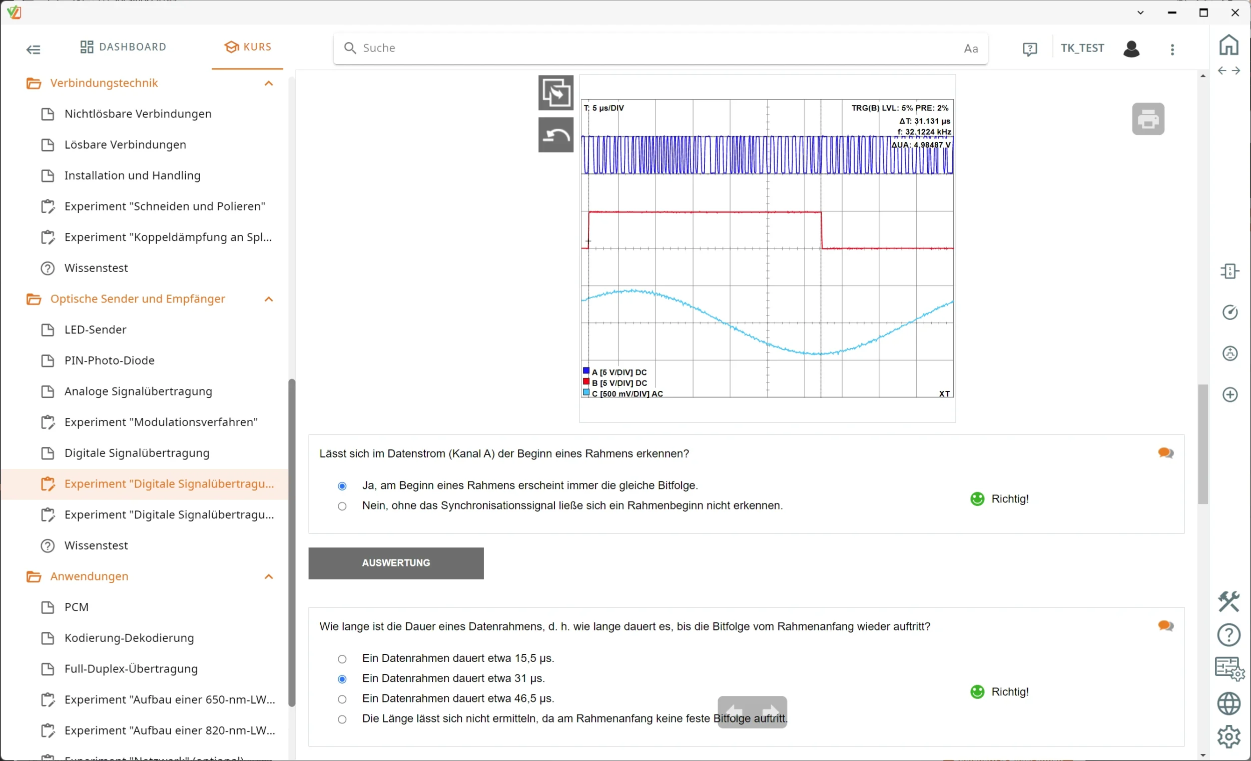
  • 2/4-channel oscilloscope — Displays modulation and received signals in the time domain, measures signal propagation times and pulse broadening, and makes attenuation visible.
  • Measuring digital data streams on the link — The BNC measuring points on the transmitter card output the digital data stream, allowing waveform, propagation time and jitter to be evaluated on the oscilloscope.
  • Practicing fiber-optic connection technology and handling — Students prepare fibers with special tools, clean the optics, make plug-in connections and measure their insertion loss.
  • Function generator — Generates sine, square-wave and triangular signals of variable frequency to drive the transmitter modules in analog and digital experiments.
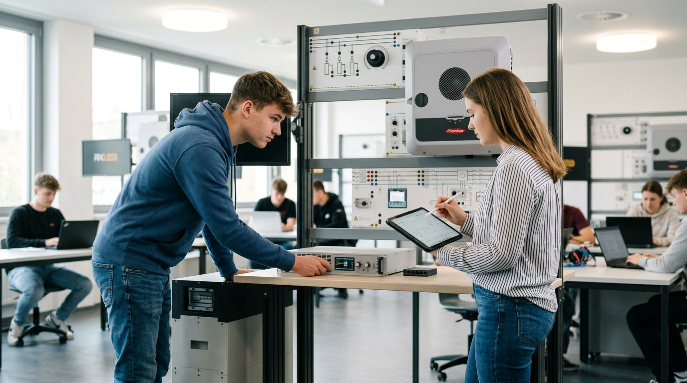
Learners working with RXLea on a tablet at a Lucas-Nuelle training system
RXLea

From Knowledge Comes Capability.

You guide the learning

Where theory and practice go hand in hand.

RXLea brings a new way of learning: project-based, hands-on and clearly structured. Learners solve real-world tasks, while instructors save time on preparation. Interactive modules, smart analytics and real hardware create a modern, efficient learning world.

Hands-on and interactive

Animations, interactive tasks and realistic scenarios build a deep understanding. All content is organized into clear learning paths for focused, hands-on learning.

Digital support

3D assembly animations and digital instructions simplify complex procedures, reduce errors and help learners work more independently.

Visual support

Overview graphics, screenshots and sample animations make the learning world transparent. Photos from the learning packages are also available, including country-specific versions where needed.

Learners using a tablet at an energy training system
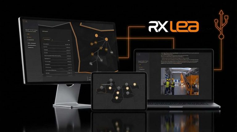
RXLea on desktop, laptop and tablet
RXLea Path Creator for building learning journeys
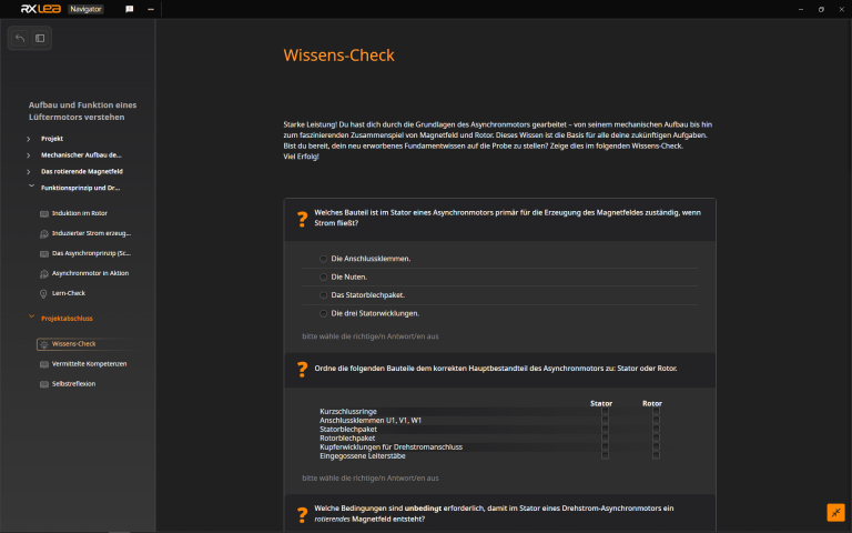
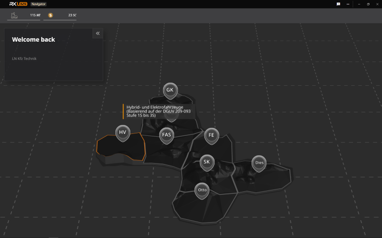
RXLea Navigator showing the learning world
Learn more about RXLea
Newsletter

Stay ahead in
technical training.

Get the latest training systems, product launches and educational insights, delivered directly to your inbox.

Your email address

By subscribing, you agree to our Privacy Policy. You can unsubscribe at any time.

 Please select at least one category before subscribing.
I'm interested in - select all that apply