


Skip to content

PCB Design with NI Ultiboard

RXLea
Digital projects for hands-on learningInteractive learning content, directly connected to the training system.

PCB Design with NI Ultiboard

BEL09UT

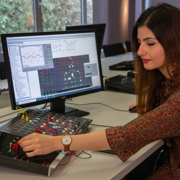
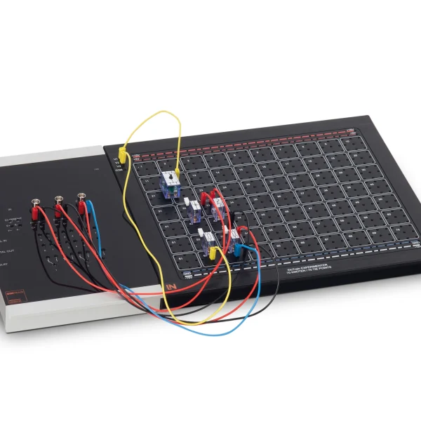
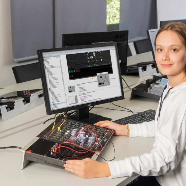
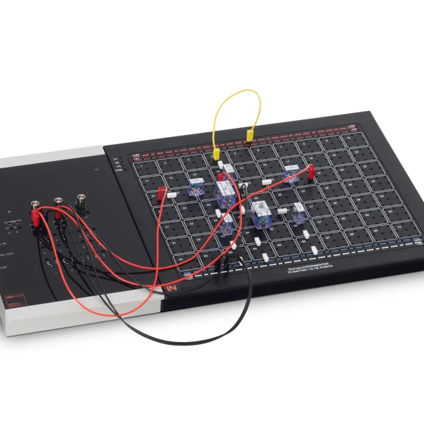
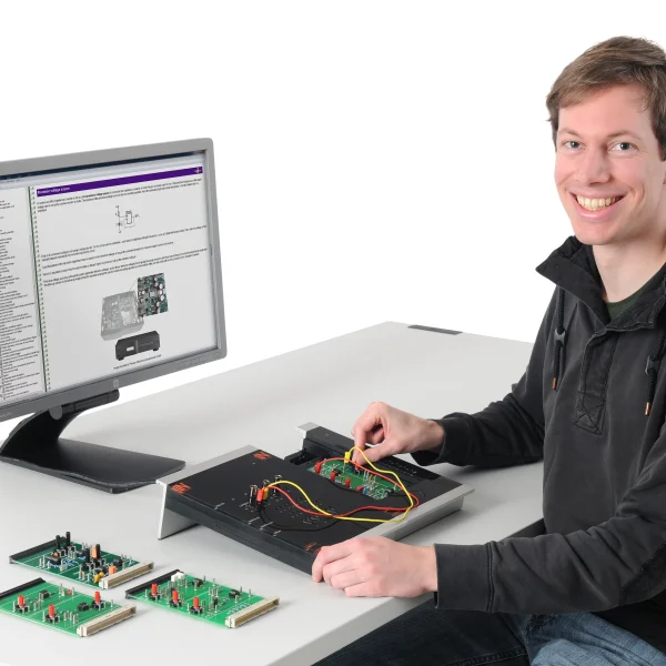
Interactive training system for designing professional PCB layouts with NI Ultiboard: from placement, routing and design rule checking to Gerber export.

Learning Content
  • Understanding PCB manufacturing
  • Applying IPC standards
  • Importing the circuit diagram
  • Designing footprints
KEY FEATURES
  • End-to-end PCB layout design with NI Ultiboard
  • Practical application of industrial IPC standards
  • Creating custom footprints
  • Production preparation via Gerber export
Speak with a Product Specialist +1 (757) 808-5696 · sales@lucas-nuelle.com

In industry, rule-compliant PCB design determines signal integrity, EMC safety and manufacturing costs. The training system covers the PCB layout process, from design rules and routing to the manufacturing file. Learners transfer circuit diagrams from NI Multisim to NI Ultiboard, define the board shape, create their own footprints, place components and route conductor tracks in compliance with standards. In doing so, they apply the IPC design rules for track spacing and insulation clearances, check the layout with the Design Rule Check and finally generate Gerber and drill data for manufacturing. This covers the complete path from circuit diagram to production-ready board.

CO4204-5VCourse - Electronics 10: PCB layout with NI Ultiboard
CO4203-2AUniTrain Interface mit virtuellen Instrumenten (Basis VI)
CO4203-2JUniTrain measurement accessories, shunts and connection cables
CO4203-2YUniTrain storage case for one UniTrain system

Learning Content in Detail

Learners work through the path from the imported circuit diagram to production-ready Gerber data.

Understanding PCB manufacturing

Learners describe historical and modern manufacturing processes such as etching or CNC milling.

Applying IPC standards

Learners determine the required track spacing and insulation clearances for each voltage class in accordance with IPC-2221.

Importing the circuit diagram

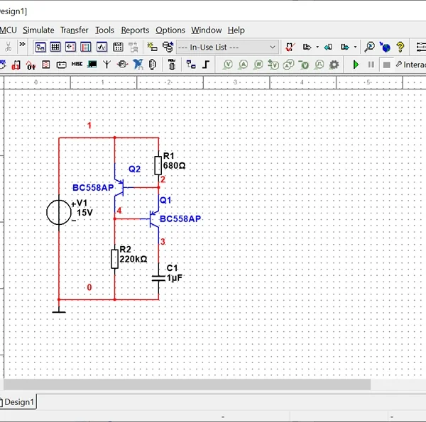
Learners adapt netlists in NI Multisim and export the circuit to NI Ultiboard without errors.

Designing footprints

Learners draw new component footprints with correct pad shapes, drill diameters and silkscreen boundaries.

Routing conductor tracks

Learners route signal and power lines manually on several layers while observing the design rules.

Generating Gerber files

Learners export finished PCB layouts to Gerber and drill formats for subsequent production.

Features & Applications

The tasks are drawn from electronics development as well as from prototype construction and PCB layout.
  • End-to-end PCB layout design with NI Ultiboard — Learners go through the complete CAD layout process, from defining the geometry and importing the netlist to the finished double-sided PCB.
  • Practical application of industrial IPC standards — Learners apply the IPC design rules for track spacing, insulation clearances and voltage classes in a practical way.
  • Creating custom footprints — Learners create their own component footprints in the editor, defining THT and SMD pads, package outlines and pin assignments.
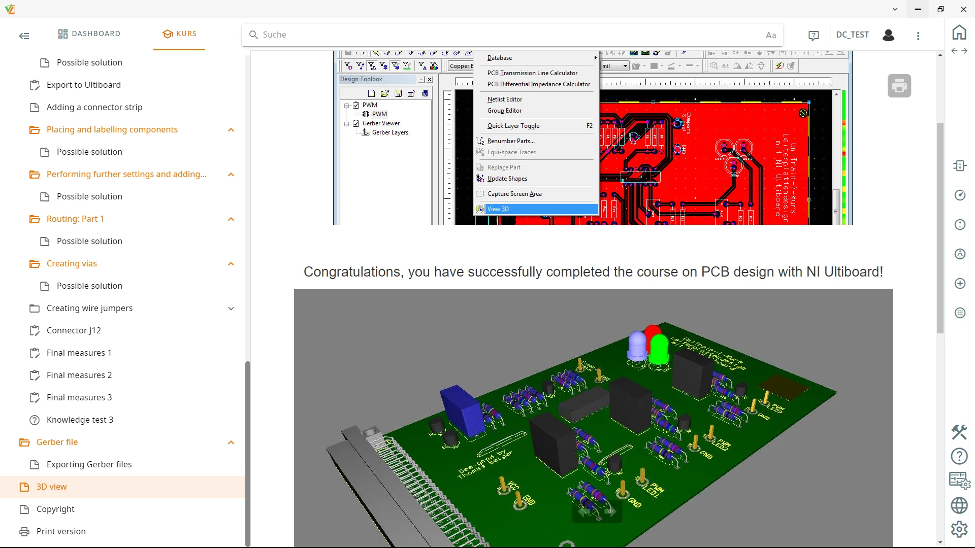
  • Production preparation via Gerber export — Learners generate the final Gerber and drill files for industrial manufacturing and for CNC PCB milling.
  • Working with inch and metric dimensions — Learners switch between thou, mil and mm, keep precisely to the inch-based pitch of the components and define the mechanical board outline to the nearest millimeter.
  • Creating custom 3D footprints — Learners design footprints with pad spacing, drill holes and silkscreen boundaries and add 3D height information for the preview.
  • EMC-compliant, signal-appropriate track routing — Learners avoid reflections by using 45° angles, keep lines short and place decoupling capacitors at an effective distance for interference suppression.
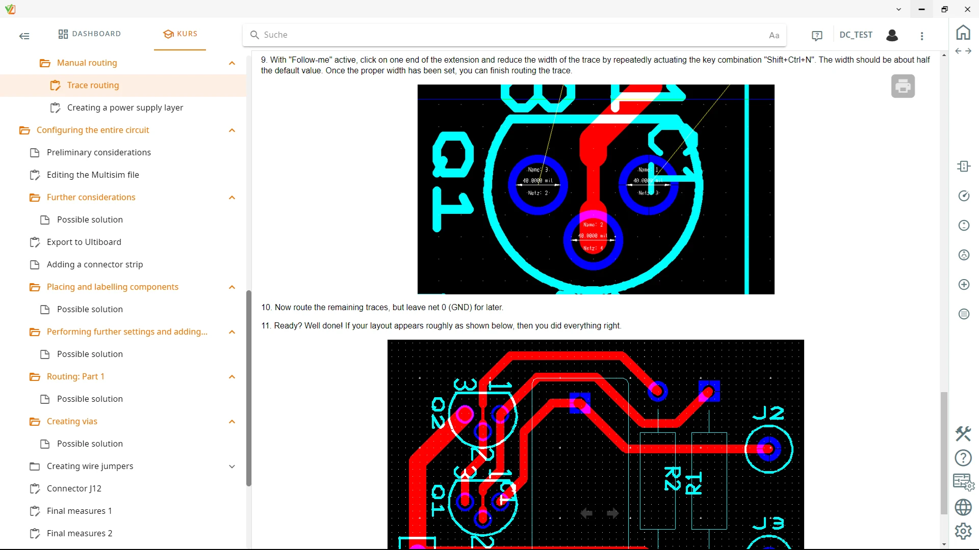
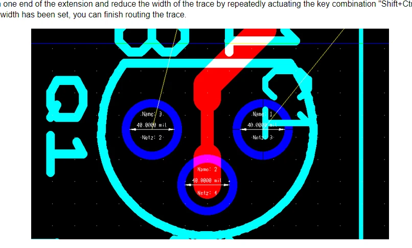
  • Targeted track narrowing at tight spots — Learners reduce the track width when routing between closely spaced IC pins in order to avoid DRC errors and maintain the required clearances.
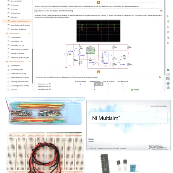
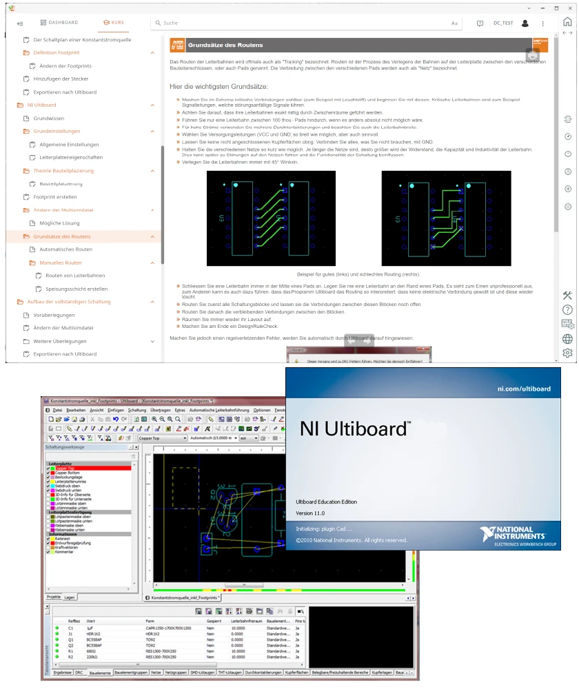
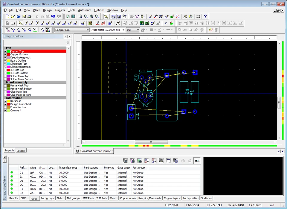
  • NI Ultiboard Education Edition software — The software offers layout tools, component libraries, autorouting functions and real-time design rule checks (DRC).
Learners working with RXLea on a tablet at a Lucas-Nuelle training system
RXLea

From Knowledge Comes Capability.

You guide the learning

Where theory and practice go hand in hand.

RXLea brings a new way of learning: project-based, hands-on and clearly structured. Learners solve real-world tasks, while instructors save time on preparation. Interactive modules, smart analytics and real hardware create a modern, efficient learning world.

Hands-on and interactive

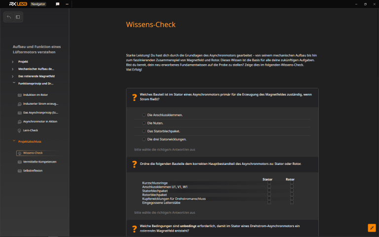
Animations, interactive tasks and realistic scenarios build a deep understanding. All content is organized into clear learning paths for focused, hands-on learning.

Digital support

3D assembly animations and digital instructions simplify complex procedures, reduce errors and help learners work more independently.

Visual support

Overview graphics, screenshots and sample animations make the learning world transparent. Photos from the learning packages are also available, including country-specific versions where needed.

Learners using a tablet at an energy training system
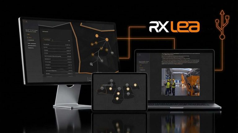
RXLea on desktop, laptop and tablet
RXLea Path Creator for building learning journeys
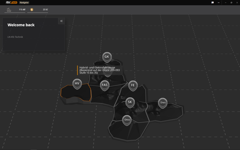
RXLea Navigator showing the learning world
Learn more about RXLea
Newsletter

Stay ahead in
technical training.

Get the latest training systems, product launches and educational insights, delivered directly to your inbox.

Your email address

By subscribing, you agree to our Privacy Policy. You can unsubscribe at any time.

 Please select at least one category before subscribing.
I'm interested in - select all that apply