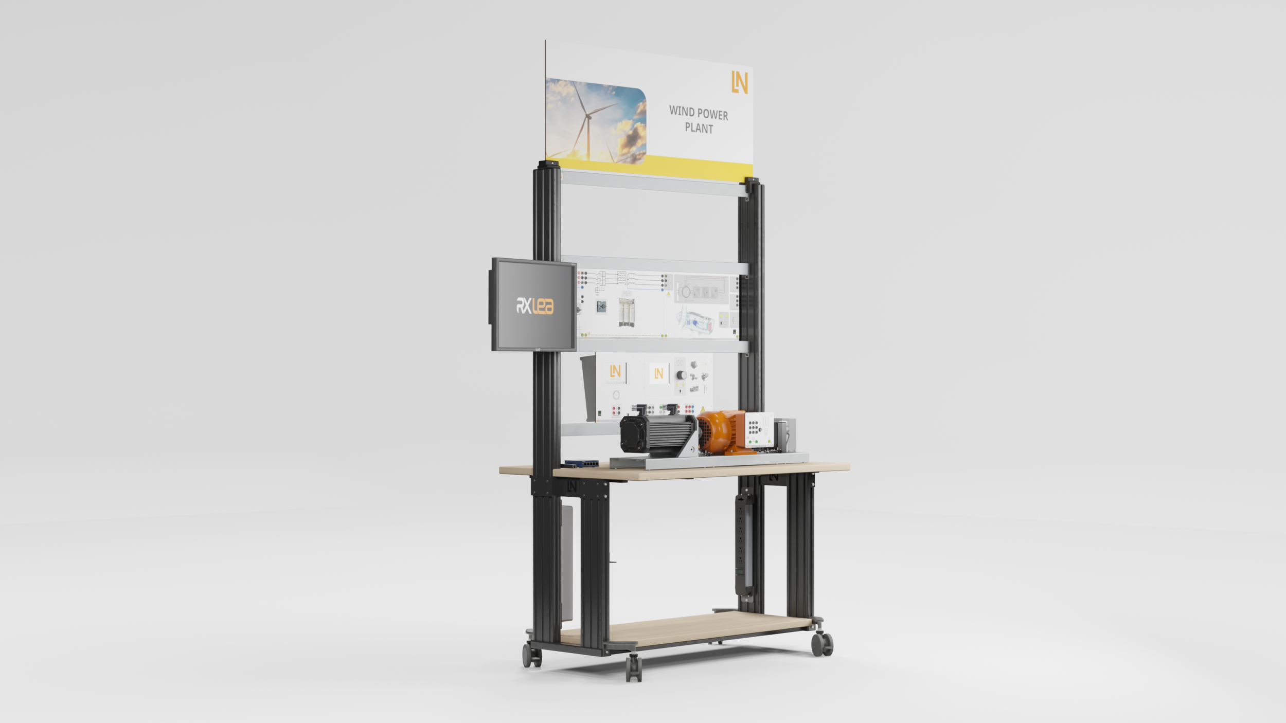



Wind Power Plant
Wind Power Plant
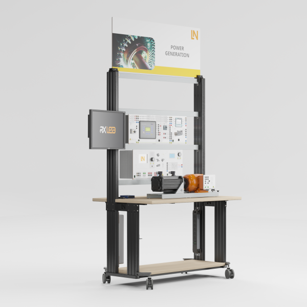
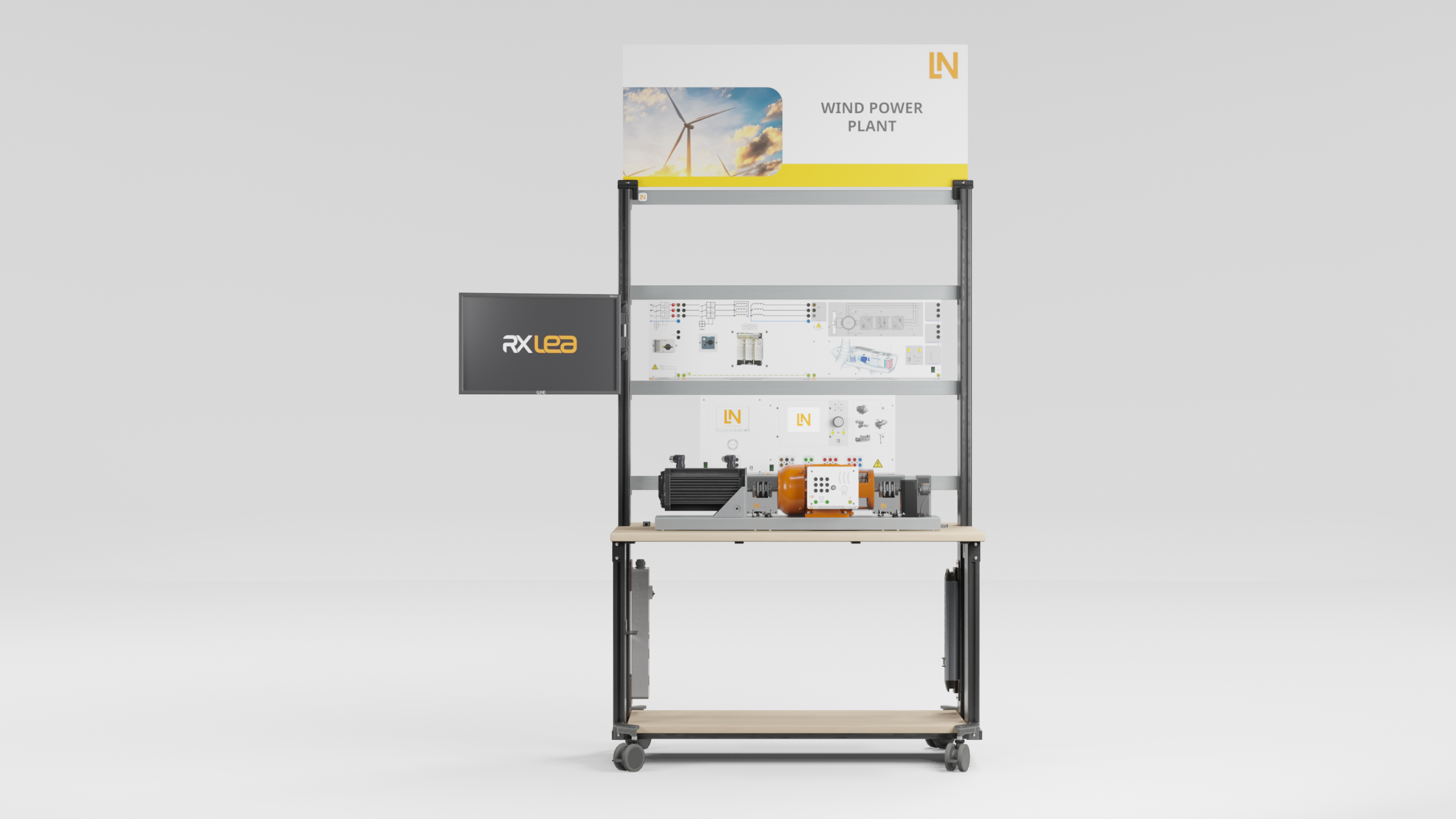
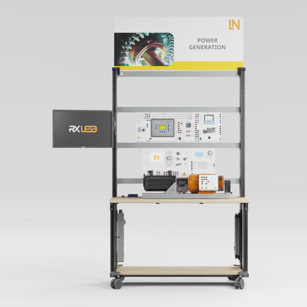
Learners explore the globally dominant DFIG technology. They emulate a wind turbine, from grid synchronization to active and reactive power control under realistic wind conditions and achieve maximum energy yield and grid contribution.
- Explaining how a DFIG wind turbine works
- Carrying out grid synchronization
- Controlling real and reactive power
- Determining optimum operating points
- Replicating the energy flow of a complete wind turbine
- Controlling the machine via the rotor circuit
- Supporting the grid with real and reactive power
- Vestas V80 as the model for the emulation
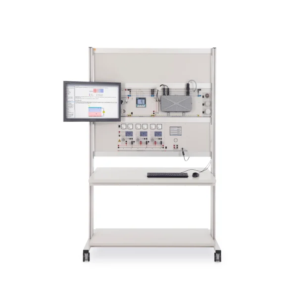
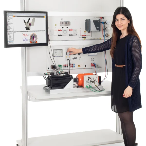
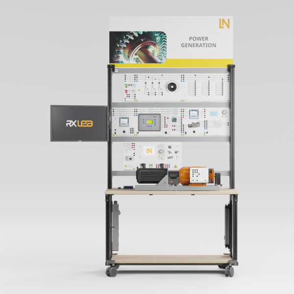
Variable-speed wind turbines in the megawatt range predominantly use doubly fed induction generators. This design exploits changing wind speeds for maximum energy yield while also supporting the power grid. The equipment replicates such a turbine in the laboratory. A servo machine test system drives the slip-ring machine and converts wind strengths, gusts, ramps and the pitch angle into mechanical torque. The DFIG controller with machine-side and grid-side converters controls the rotor circuit in both directions. Students synchronize manually and automatically, operate the machine in sub- and super-synchronous mode, specify real and reactive power and evaluate the phase angles in the phasor diagram.
| Base Product | |
| CO3208-3A7 | Control unit for wind turbine, double-fed asynchronous generator |
| SE2682-6W7 | Three-phase multi-function machine, 1.0kW |
| CO3208-3B7 | 3-phase isolation transformer, 1kW for wind power plants |
| SE2682-5T | Incremental position encoder 1024 pulses |
| SE2662-6A | Rubber coupling sleeve, 1kW |
| SE2662-7D | Coupling guard with LED lighting for 1kW machines |
| SO2800-3R7 | Interactive Lab Assistant: Windkraftanlagen mit DFIG |
| Add-on | |
| CO5127-2S | Power Quality Meter mit Grafikdisplay und Langzeitspeicher |
| CO3301-5R | Double busbar unit, three-phase, incoming / outgoing feeder |
| LM9057 | Patch cable Cat5E 1x 1m yellow, 2x 2m yellow |
| LM8257 | USB 2.0 Ethernet adapter, 10/100 |
| LM9988-8 | 5-Port Ethernet Switch (International) |
| SO5148-1Z | Set of safety measurement cables, 4mm, 10m, 5 pcs, incl. fastening |
| CO3301-3Z | Adjustable 3-phase power supply, 0-450V/2A |
| CO3212-5V | Three-phase power supply with motor protection switch |
| Power Supply | |
| CO3212-5V7 | Three-phase power supply with motor protection switch |
| Measuring Instruments | |
| CO5127-2A | Power-Multimeter |
| Accessories | |
| CO3636-6Y7 | Servo machine test stand for 1kW machines incl. software ActiveServo (D,GB,F,E) |
| SE2662-7D | Coupling guard with LED lighting for 1kW machines |
| SE2662-6A | Rubber coupling sleeve, 1kW |
| Furniture | |
| ST8010-4G | Keyboard adapter for flat screen monitor holders |
| ST8008-8N7 | Protected power distribution for workstations |
| ST8010-4J8 | Multiple power outlet strip, 6 outlets, US-standard |
| Furniture Accessories | |
| ST8000-4D | Display for Wind Power Plants equipment |
| Measurement Leads | |
| SO5126-3R | Safety connecting plug 4mm with tap (2x), black, 1000V/32A CAT II |
| SO5126-3W | Safety connecting plug 4mm with tap (2x), green/yellow, 1000V/32A CAT II |
| SO5126-3V | Safety connecting plug 4mm with tap (2x), blue, 1000V/32A CAT II |
| SO5148-1L | Set of safety measurement cables, 4mm (31 leads) |
Learning Content in Detail
Explaining how a DFIG wind turbine works
Carrying out grid synchronization
Controlling real and reactive power
Determining optimum operating points
Features & Applications
- Replicating the energy flow of a complete wind turbine — The servo machine test system handles the wind simulation, passing variable wind strengths and gusts to the generator as torque. The generator’s control unit controls the machine and feeds the energy into the grid.
- Controlling the machine via the rotor circuit — At the heart of the equipment is a real doubly fed induction generator in the form of a slip-ring machine with its own control unit. Students explore the key principle of the technology: control via the rotor circuit at constant grid frequency over a wide speed range.
- Supporting the grid with real and reactive power — After grid synchronization, students use the WindSim software to specify setpoints for real and reactive power, thereby influencing the stability of the power grid in a targeted way.
- Vestas V80 as the model for the emulation — WindSim replicates the operating and control behavior of a real industrial turbine. Start-up, grid synchronization and operation behave like the original in terms of speed, power control and pitch correction, which ensures transferability to wind farms.
- DFIG control unit as a converter system — The control unit represents the power electronics with machine-side and grid-side converters and enables bidirectional energy flow in the rotor circuit. Students analyze how energy is drawn for excitation at subsynchronous speed and how power is fed in at supersynchronous speed.
- Servo test system as a dynamic wind simulator — Together with WindSim, the test system acts as the prime mover and emulates the wind rotor. Students specify constant winds, gusts, ramps or user-defined profiles as well as the pitch angle and obtain reproducible test conditions.
- WindSim as a virtual control room — The software acts as the turbine’s SCADA system. Students create wind profiles and import them from real weather data, adjust the pitch angle, start automatic grid synchronization, specify power setpoints and track all operating parameters in the characteristic diagram.
- DFIG control and synchronizer — With these virtual instruments, students control the generator manually: they generate a stator voltage via the rotor frequency and rotor current and, using the synchronizer, match frequency, amplitude and phase angle with the grid before connecting.
- Power control for analyzing energy flows — The instrument graphically displays the real and reactive power flows between the stator, the rotor with machine-side converter and the grid with grid-side converter. Students specify power values and immediately see how the flows are distributed.
- Vector view of currents and voltages — The Phasor View shows the currents and voltages of the stator, rotor and grid as a phasor diagram in the d/q coordinate system. Students use it to investigate how real and reactive power control shifts the phase angle of the stator current, and gain an understanding of the principle of vector control.

From Knowledge Comes Capability.
You guide the learning
Where theory and practice go hand in hand.
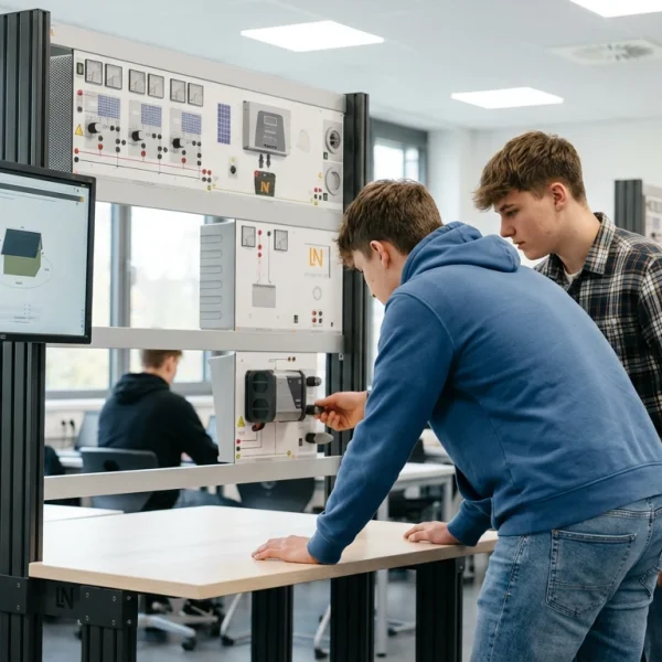
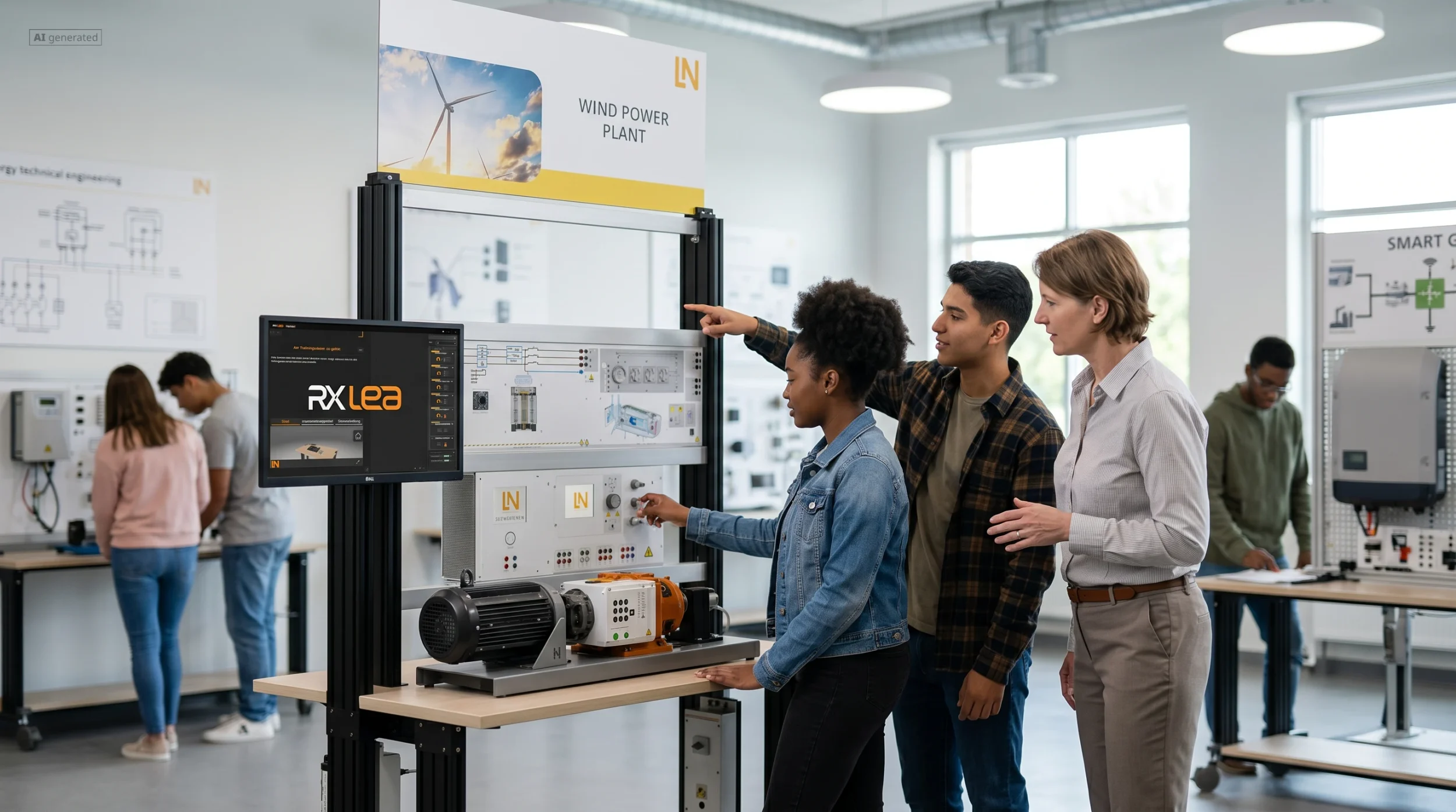
RXLea brings a new way of learning: project-based, hands-on and clearly structured. Learners solve real-world tasks, while instructors save time on preparation. Interactive modules, smart analytics and real hardware create a modern, efficient learning world.
Hands-on and interactive
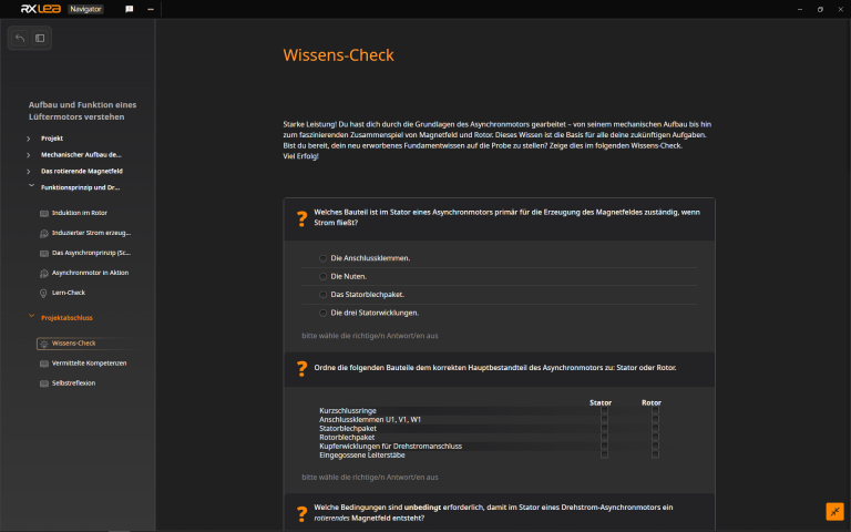
Animations, interactive tasks and realistic scenarios build a deep understanding. All content is organized into clear learning paths for focused, hands-on learning.
Digital support
3D assembly animations and digital instructions simplify complex procedures, reduce errors and help learners work more independently.
Visual support
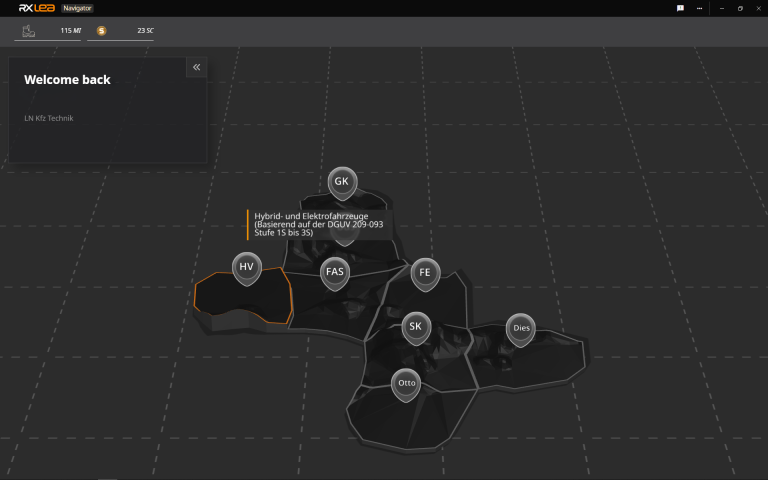
Overview graphics, screenshots and sample animations make the learning world transparent. Photos from the learning packages are also available, including country-specific versions where needed.


Stay ahead in
technical training.
Get the latest training systems, product launches and educational insights, delivered directly to your inbox.