

IMU with Subsystem Painting
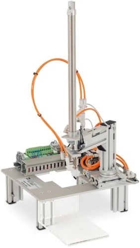
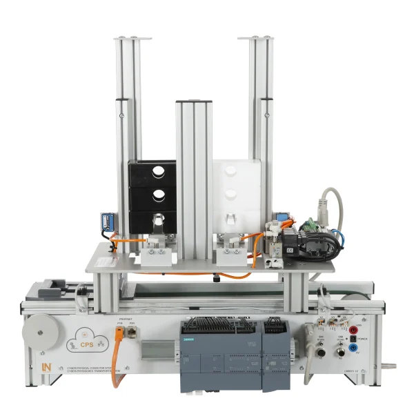
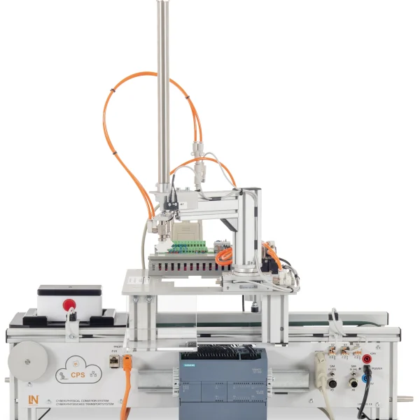
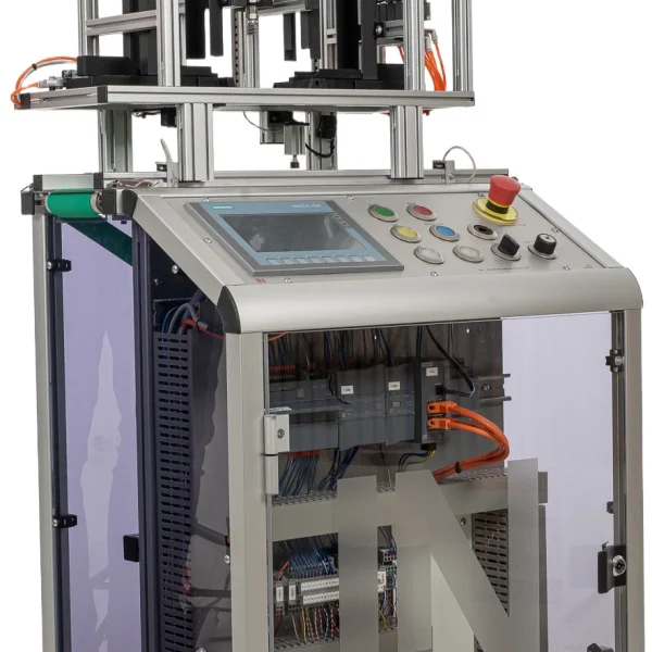
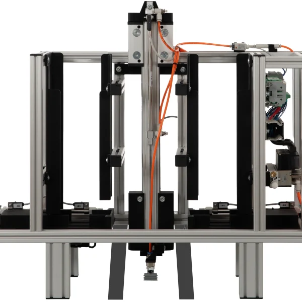
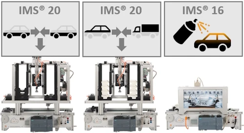
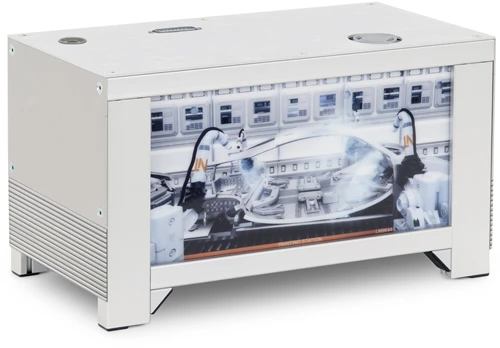
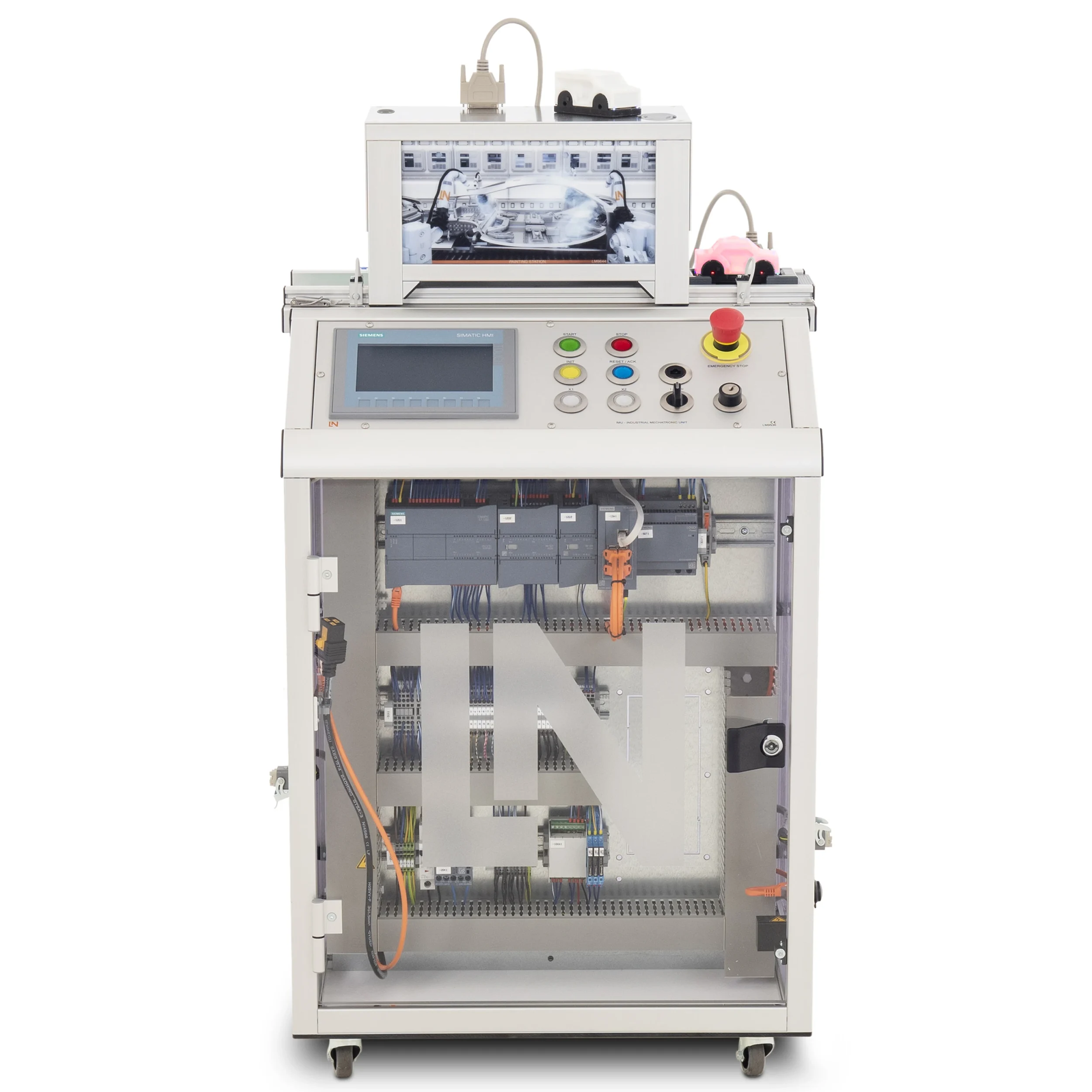
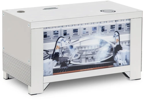
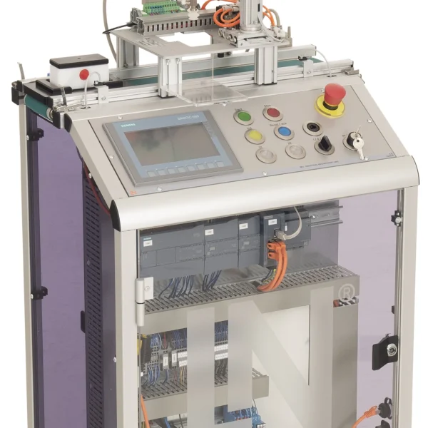
Using the painting subsystem, the mobile Industrial Mechatronic Unit controls an automated booth with two door motors, a fan and LED color simulation. Programming is done in FBD and Structured Text.
- Controlling the door motors
- Outputting a 4-bit color code
- Developing an FBD step sequence
- Applying Structured Text
- Automating booth and door control
- Making painting visible with RGB LEDs
- Flexible 4-bit color coding
- Color selection and status on the touchscreen
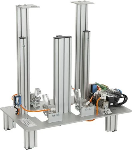
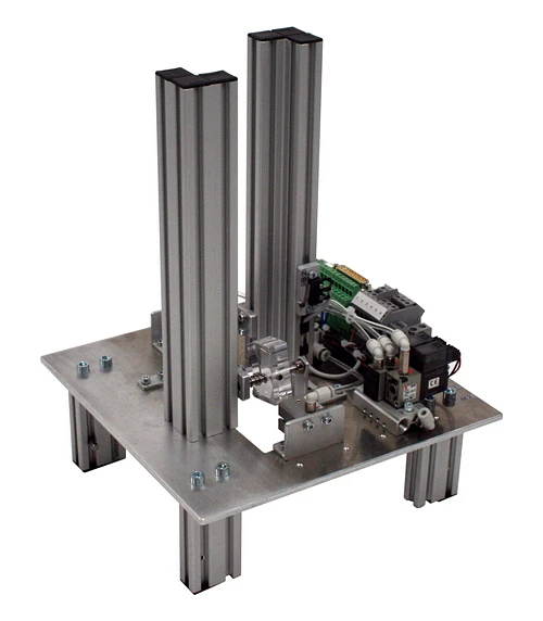
Automated painting systems combine door control, ventilation and paint application in a tightly timed process. The painting subsystem replicates this sequence on a training scale: two DC motors open and close the booth doors, four limit switches report the end positions, a proximity switch detects the car body in the booth and a fan simulates the extraction system. Via four digital outputs, the PLC transfers a 4-bit color code to an Arduino Nano, which controls 52 RGB LEDs and makes the paint application visible. Learners develop the sequence once in FBD and once in Structured Text, configure the color selection on the KTP700 and adapt the C/C++ code of the microcontroller.
| Base Product | |
| LM9536 | Industrial Mechatronic Unit |
| LM9532 | Film, for oscilloscope cameratype LM 7000 |
| SO6200-2U | QuickChart, IPA 1 Compact station (GB) |
| LM9644 | Painting station |
| LM9066 | Interface cable 25-pin, Sub-D socket / plug 1m |
| SO6200-2V | QuickChart IMS 16 Mechatronics Painting Station |
| Course | |
| SO2805-5J | Interactive Lab Assistant: IMU 1 Industrial Mechatronic Unit |
| SO2805-5Q | Interactive Lab Assistant: IMS 16 Painting station |
| SO2805-5Y | Interactive Lab Assistant: Web-Link of Cyber-Physical Systems |
| Accessories | |
| LM9562 | Battery for the car / van PCB |
| LM9573 | Van body for PCB with display |
| LM9574 | Car body for PCB with display |
| LM9576 | PCB with display for automotive production |
| LM9577 | Chassis of the car / van with display |
| LM9558 | WiFi Router |
Learning Content in Detail
Controlling the door motors
Outputting a 4-bit color code
Developing an FBD step sequence
Applying Structured Text
Configuring the Arduino microcontroller
Designing HMI interfaces
Controlling speed via PWM
Carrying out fault diagnosis
Features & Applications
- Automating booth and door control — Two DC motors open and close the booth doors automatically, safeguarding the painting and drying process.
- Making painting visible with RGB LEDs — An integrated Arduino Nano controls 52 RGB LEDs, simulating dynamic paint application in single-color or multi-color patterns.
- Flexible 4-bit color coding — Via four digital PLC outputs, the controller transmits up to 13 different color variants as well as the start signals to the booth.
- Color selection and status on the touchscreen — On the touch panel, learners select the color from drop-down menus, switch the operating mode and follow the status in real time.
- Programming in FBD and Structured Text — Learners develop the same sequence in Function Block Diagram and in Structured Text and compare the two implementations directly.
- Arduino Nano as microcontroller — The integrated microcontroller processes the PLC’s 4-bit color code and controls the Adafruit NeoPixel LEDs.
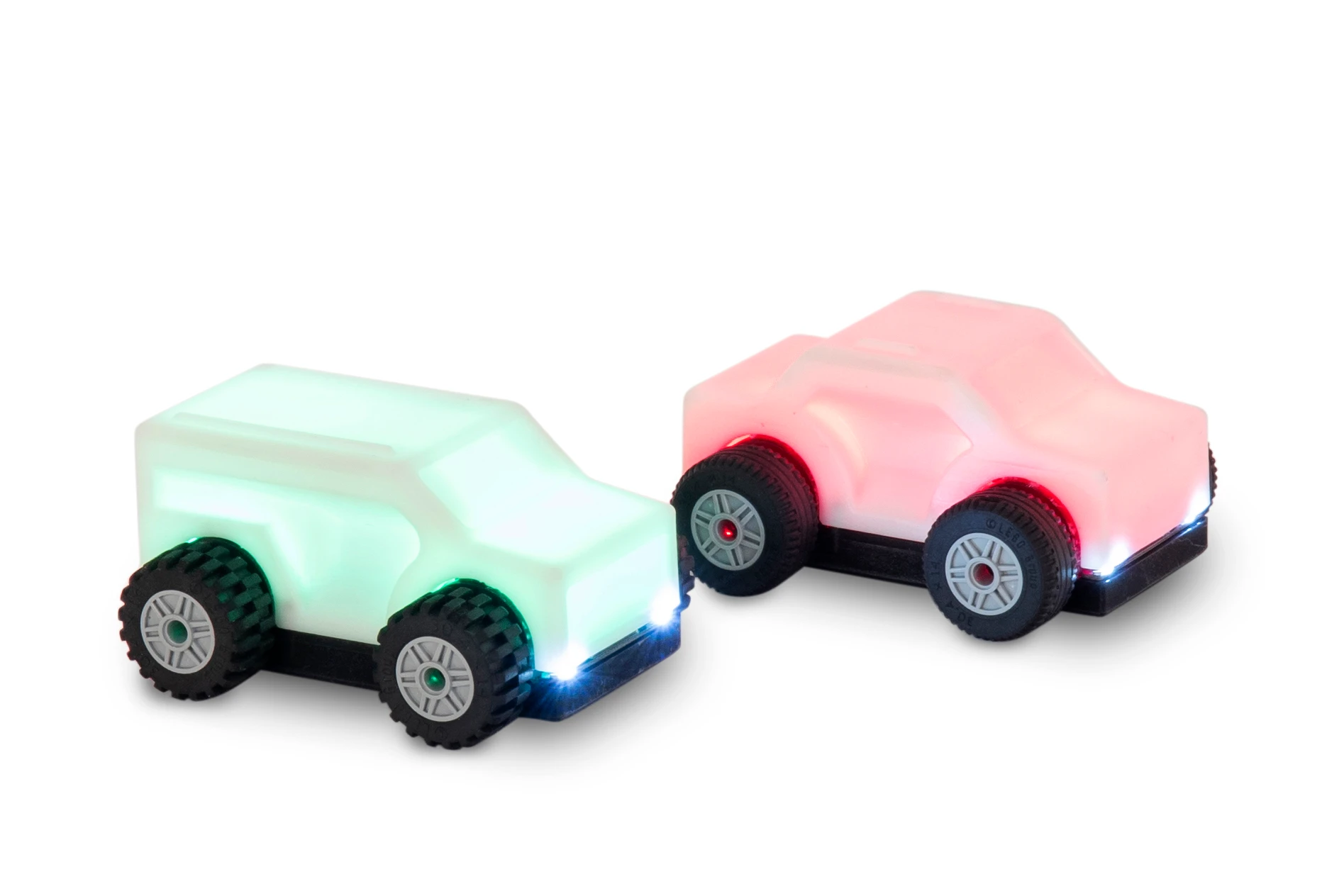
- IIoT connection of the vehicles — The PLC communicates with the cars via Wi-Fi and REST interfaces in order to paint them in individual colors.
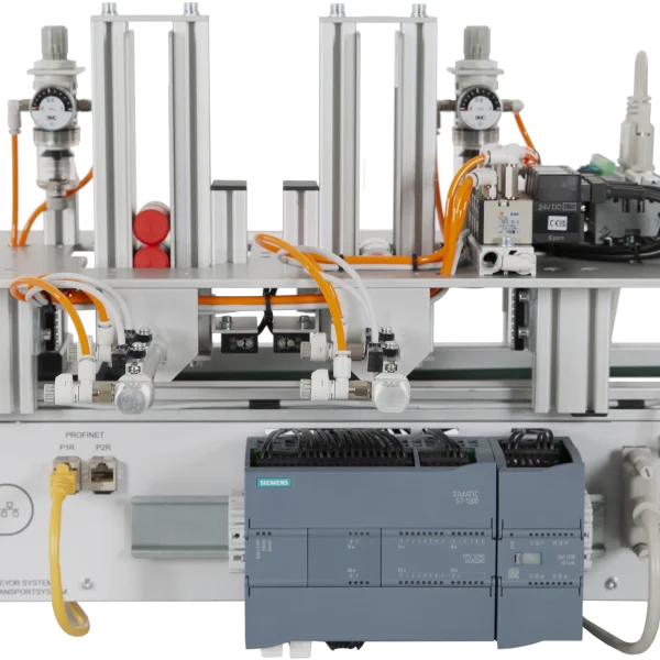
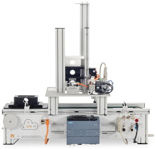
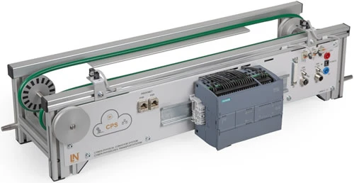
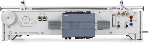
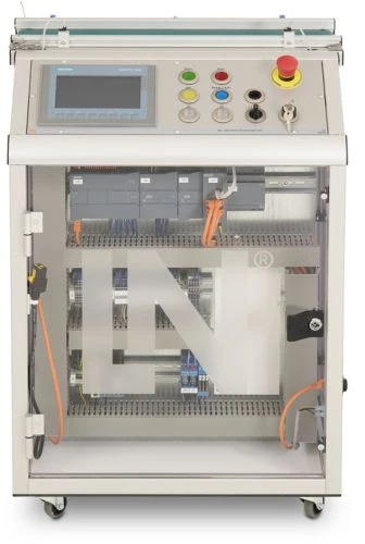
- Siemens S7-1215C with signal board — The PLC coordinates the door motors, fan and conveyor belt, evaluates the position sensors and transmits the 4-bit color code.
- SIMATIC KTP700 Basic Panel (CO3713-4Q) — The panel enables recipe selection, color selection via drop-down menu and visualization of the booth status.
- Electric motor door drives — Two 24 V DC motors drive the entry and exit doors of the paint booth.
- Four door limit switches — The mechanical microswitches detect the open and closed end positions of both booth doors.
- Proximity switch for the vehicle position — The switch detects when the vehicle body arrives in the booth and enables the doors to close and the painting sequence to start.
- Booth fan and Arduino Nano — The 24 V fan simulates the extraction system, while the microcontroller drives the 52 NeoPixel LEDs for the painting simulation.
- 25-pin transfer module — The module bundles all sensor signals, limit switches and actuator commands of the paint booth and connects them to the PLC with reverse polarity protection.
- Siemens TIA Portal and STEP 7 — Engineering environment for sequences in FBD and ST and for configuring the I/O interfaces.
- WinCC Graphics and KTP700 configuration — Configuration tool for HMI user interfaces with color drop-downs and status displays.
- Arduino IDE with Adafruit NeoPixel library — Development environment for creating and adapting the C/C++ code for the LED control of the microcontroller.

From Knowledge Comes Capability.
You guide the learning
Where theory and practice go hand in hand.
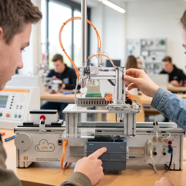
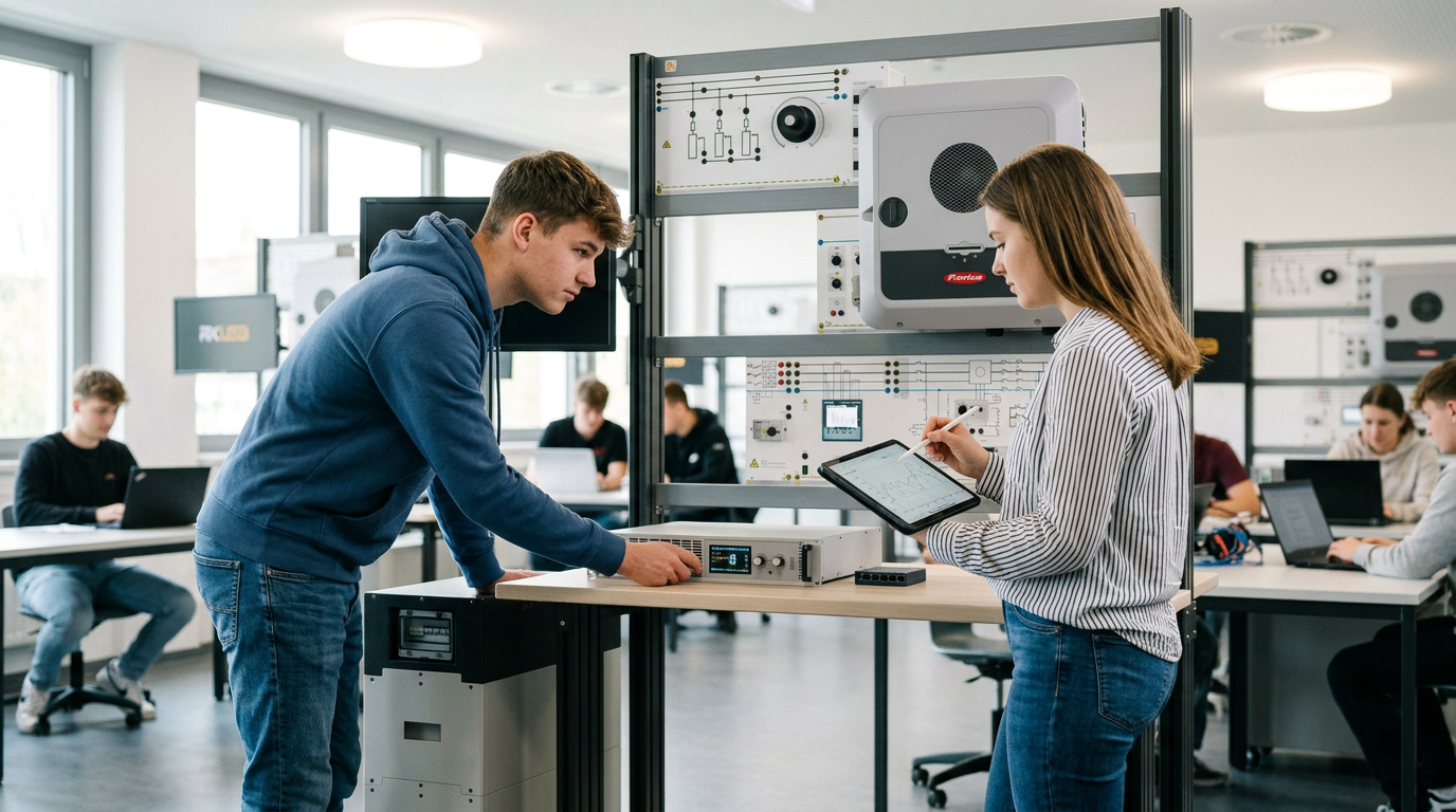
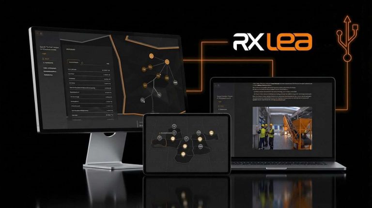
RXLea brings a new way of learning: project-based, hands-on and clearly structured. Learners solve real-world tasks, while instructors save time on preparation. Interactive modules, smart analytics and real hardware create a modern, efficient learning world.
Hands-on and interactive
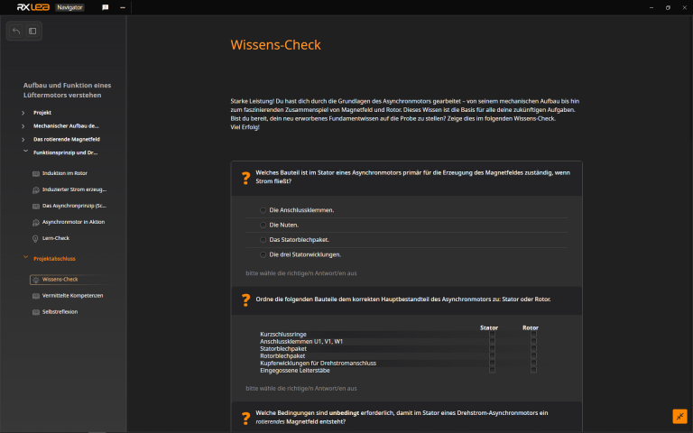
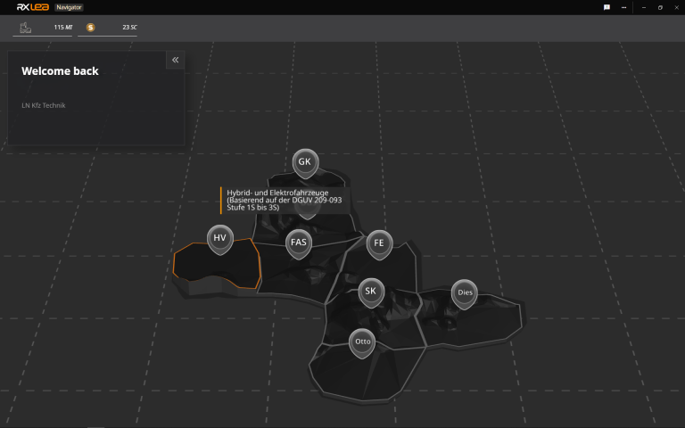
Animations, interactive tasks and realistic scenarios build a deep understanding. All content is organized into clear learning paths for focused, hands-on learning.
Digital support
3D assembly animations and digital instructions simplify complex procedures, reduce errors and help learners work more independently.
Visual support
Overview graphics, screenshots and sample animations make the learning world transparent. Photos from the learning packages are also available, including country-specific versions where needed.

Stay ahead in
technical training.
Get the latest training systems, product launches and educational insights, delivered directly to your inbox.